TM 9--2815--247--34
0059 00--3
CYLINDER HEAD ASSEMBLY REPLACEMENT -- CONTINUED
0059 00
Removal -- Continued
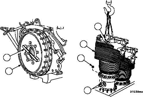
7. Rotate maintenance stand so cylinder head assembly (1) is vertical.
8. Install engine turning tool (6) on engine flywheel (7).
NOTE
Before removing each cylinder head assembly, the crank-
shaft must be turned to position the piston of the cylinder
head assembly being removed to top center. Make cer-
tain each piston is properly positioned before attempting
cylinder head assembly removal. The following pairs of
pistons are at top center together: 1R and 6R, 2R and
5R, 3R and 4R, 1L and 6L, 2L and 5L, and 3L and 4L.
9. Attach sling to top of cylinder head assembly (1) using two 7/16 X 1 1/4--inch (11.11x31.75mm) screws (8).
10. Remove last two cylinder base nuts (4) from cylinder head assembly (1).
WARNING
11. Carefully lift cylinder head assembly (1) until it is just above piston pin bore (9).
Figure 5
1
8
9
4
7
6
|
|