TM 9--2815--247--34
0061 00--4
CYLINDER HEAD ASSEMBLY REPAIR -- CONTINUED
0061 00
Disassembly -- Continued
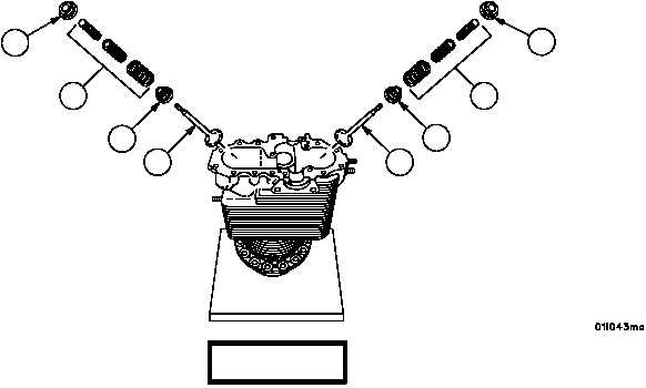
10. Remove exhaust valve spring seat (7), three springs (6), and rotor (15) from exhaust valve (9).
11. Remove valve spring lock (12), three springs (11), and seat (16) from intake valve (13).
Figure 9
9
15
7
6
13
16
11
12
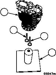
CAUTION
Make certain valves do not drop out when removing cylin-
der from valve removing and inserting stand or damage
could occur.
12. Remove cylinder head assembly (1) from valve removing and inserting stand (2), place cylinder head assembly
(1) on its side and remove intake valve (13) and exhaust valve (9) through the cylinder bore.
Figure 9
2
9
1
13
|
|