|
|
|
|

|
TM 9--2815--247--34
0015 00--5
INTAKE AND EXHAUST VALVE AND METERING PUMP TIMING --
CONTINUED
0015 00
Test -- Continued
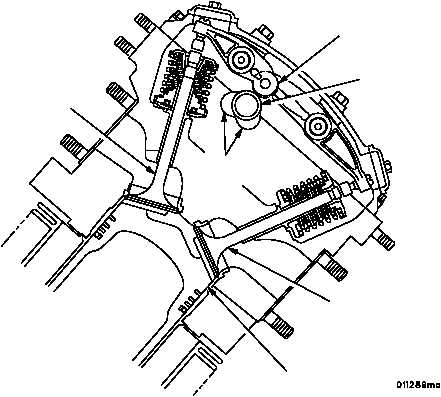
7. Turn flywheel until cylinder 6R valves are closed and camshaft lobes are in the position shown.
Figure 10
VALVE ROCKER
ROLLERS
CAMSHAFT
PISTON (T.D.C.)
INTAKE VALVE
(CLOSED)
CAMSHAFT
LOBES
EXHAUST VALVE
(CLOSED)
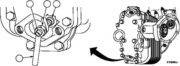
8. Using thickness gauge blade (15), set cylinder 6R intake valve clearance to 0.100 inch (2.5 mm) by turning the
adjusting screw (16) clockwise to decrease the clearance or counterclockwise to increase the clearance.
9. Check position of valve adjusting screw pad (17) to make sure seat is flat on valve stem.
10. Tighten adjusting screw nut (18) to 200--225 lb--in (22.6--25.4 NSm).
Figure 9
15
16
17
18
|
|
|
|
|
Privacy Statement -
Copyright Information. -
Contact Us