TM 9-2815-250-24&P
3-9.
PISTON AND COMBUSTION CHAMBER LINER REPAIR (continued).
d.
ASSEMBLY
NOTE
Piston head must be installed so the pocket is on the same side of the piston
assembly as the notches in the connecting rod and connecting rod cap.
1.
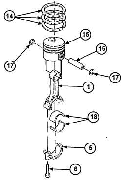
If piston (15) is being replaced, place piston (15)
on connecting rod (1) with pocket in piston (15)
facing
the
same
direction
as
notches
in
connecting rod (1). Install piston pin (16) in
piston (15) and connecting rod (1) and secure
with two new retaining rings (17). Repeat for
other piston, if necessary.
NOTE
There are two pistons on the engine.
Repeat steps 2 and 3 for each of
them.
2.
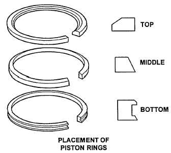
Install three piston rings (14) on piston (15).
See diagram for correct location and orientation
of piston rings. Stagger three ring gaps so they
are 120 degrees apart and no ring gap is over
piston pin (16) or directly above or below other
ring gaps.
3.
Remove two screws (6) and connecting rod cap
(5) from connecting rod (1). Place two new
sleeve bearing halves (18) in connecting rod (1)
and connecting rod cap (5).
3-35
|
|