ARMY TM 9-2815-255-24
AIR FORCE TO 38G1-95-2
MARINE CORPS TM 2815-24/4
NOTE
Very light score marks can be found, but are acceptable if valve lift is within specification.
Pitting or galling dictates replacement. Refer to paragraph 3-32.2. for valve lift measurement.
c.
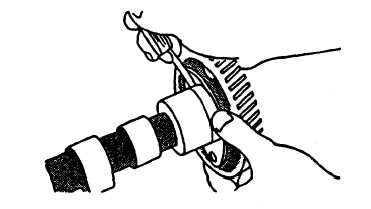
Measure camshaft thrust plate clearance as follows:
NOTE
Thrust plate clearance determines camshaft end play.
(1)
Check thrust plate clearance using a feeler gage, refer to FIGURE 3-110.
(2)
New part clearance is 0.003 to 0.009 inch (0.08 to 0.23 mm). Maximum allowable clearance is 0.015 inch
(0.38 Tim). Replace parts as necessary.
FIGURE 3-110. Measuring Thrust Plate Clearance
d.
Measure camshaft journals as follows:
(1)
Use a micrometer to take measurements, refer to FIGURE 3-111.
(2)
New camshaft journal diameter is 2.200 to 2.201 inches (55.87 to 55.90 mm). Maximum wear tolerance is
0.001 inch (0.025 mm).
(3)
If a camshaft journal diameter is less than 2.199 inches (55.85 mm), install a new camshaft.
(4)
Measure camshaft bearing bore diameter in cylinder block; 2.204 to 2.205 inches (55.98 to 56.01 mm).
Maximum clearance between bore and camshaft journal; 0.007 inch (0.18 mm).
3-161
|
|