ARMY TM 9-2815-256-24
AIR FORCE TO 38G1-96-2
MARINE CORPS TM 2815-24/5
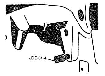
FIGURE 3-60. Flywheel Locking Tool
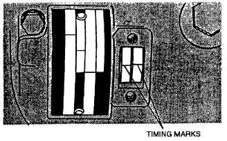
FIGURE 3-61. Checking Timing Marks
NOTE
If timing marks are as illustrated in FIGURE 3-61, insert timing tool (JDE-81-4) into flywheel, refer to
FIGURE 3-60.
k.
Check alignment of governor weight retainer and cam ring timing marks, refer to FIGURE 3-61.
NOTE
If timing cover is removed, proceed to step 1. If timing cover is not removed, proceed to step m.
I.
The following steps cover injection pump removal with timing cover removed, refer to FIGURE 3-62.
(1). Attach gear puller (JDG670) to injection pump gear and push pump from gear, refer to FIGURE 3-63.
(2). Support weight of injection pump (22, FIGURE 3-59) and remove nuts (19), lockwashers (20), and washers
(21) securing injection pump (22) to front plate. Discard lockwashers.
(3). Remove pump from mounting studs (25). Proceed to step n.
3-85
|
|