ARMY TM 9-2815-256-24
AIR FORCE TO 38G1-96-2
MARINE CORPS TM 2815-24/5
m.
The following steps cover injection pump removal with timing cover installed.
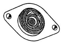
(1). Remove injection pump cover plate from timing gear cover, refer to FIGURE 3-62, cover shown removed.
FIGURE 3-62. Fuel Infection Pump Gear Access (Cover Removed)
NOTE
Be careful not to drop nut and/or washer inside engine.
(2). Remove nut and washer securing fuel injection pump drive gear to shaft.
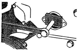
(3). Install injection pump drive gear puller (JDG670) to injection pump gear and shaft. Follow mounting
instructions provided with tool set, refer to FIGURE 3-63.
Warning
If nuts (19, FIGURE 3-59) are removed prior to shaft/gear separation, fuel injection pump will fall out
which can cause personal injury and/or equipment damage.
(4). Loosen three nuts (19, FIGURE 3-59) several turns to permit pump shaft/drive gear separation.
(5). Tighten large hex head capscrew on puller clockwise until pump shaft is loosened from tapered bore of drive
gear.
FIGURE 3-63. Separating Gear and Shaft
(6)
Support weight of fuel injection pump (22) and remove three nuts (19), lockwashers (20), and washers (21)
securing injection pump to front plate. Discard lockwashers.
3-86
|
|