ARMY TM 9-2815-256-24
AIR FORCE TO 38G1-96-2
MARINE CORPS TM 2815-24/5
(2)
Place pump housing on an arbor press with mounting flange upward. Be sure housing rests flat on arbor ,
press plate.
(3)
Position installation tool with seal above pump housing and press seal into reduced diameter at bottom of
housing bore.
(4)
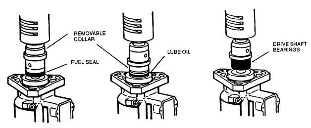
Place oil seal (45, FIGURE 3-73) at opposite end of installation tool with lip of removable collar inside seal
case (garter spring side faces tool), refer to FIGURE 3-92.
FIGURE 3-92. Installing Seals and Bearing
(5)
Position installation tool with seal above pump housing and press seal into housing until it bottoms with no
excessive force.
(6)
Remove the collar from installation tool. Slide bearing (46, FIGURE 3-73) onto tool in place of collar. Bearing
must be placed with part number facing against tool shoulder, refer to FIGURE 3-92.
(7)
Position installation tool with bearing above pump housing and press bearing into housing until it bottoms.
Check rollers for free movement.
CAUTION
To prevent damage to the teflon seal when installing drive shaft (42, FIGURE 3-73), use protection
tube supplied in bearing and seal kit.
(8)
Slide protection tube (refer to FIGURE 3-93) over the drive shaft (42, FIGURE 3-73) and insert into drive end
of pump housing until largest diameter of shaft is flush with bearing (46).
(9)
Remove protection tube from inside housing. discard tube, do not reuse it.
(10)
Using snap ring Pliers, install thrust bearing (41) into counter bore located in neck of housing.
(11)
Slide thrust washer (40), aligned with flat, and then spring washer (39) onto drive shaft. Secure with retaining
ring (38).
3-112
|
|