ARMY TM 9-2815-256-24
AIR FORCE TO 38G1-96-2
MARINE CORPS TM 2815-24/5
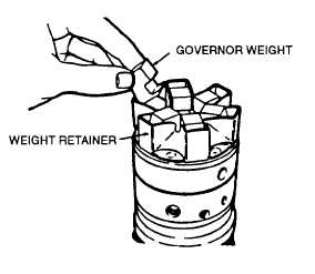
FIGURE 3-95. Installing Weights
NOTE
The two deep grooves of sleeve (19, FIGURE 3-73) should face upward. Sight across tops of
assembled weights. They should be level and collapsed against thrust sleeve.
am.
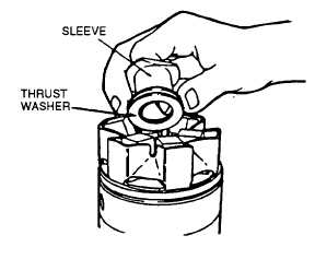
Insert governor thrust washer (20, FIGURE 3-73) and sleeve (19) into lower slots of weights (18) by tilting
weights outward slightly, refer to FIGURE 3-96.
FIGURE 3-96. Installing Thrust Washer and Sleeve
an.
Apply a light film of clean general purpose grease (630AA) to preformed packing (21, FIGURE 3-73) and install
in groove in hydraulic head.
ao.
Apply a light film of general purpose grease (630AA) around inside edge of housing and tilt housing slightly
downward at rear to aid in assembly.
ap.
Rotate cam ring (24) so threaded hole is in line with metering valve bore. This ensures proper position of cam.
3-114
|
|