ARMY TM 9-2815-256-24
AIR FORCE TO 38G1-96-2
MARINE CORPS TM 2815-24/5
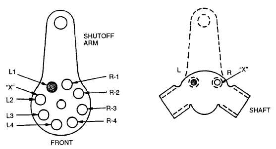
FIGURE 3-101. Alignment of Shutoff Arm
bi.
Install two new washers (22) and rubber seal rings (21) using suitable tool on throttle shaft (18) and shutoff
lever shaft (30). Apply a light film of general purpose grease (630AA) to each seal.
bj.
Install throttle shaft assembly (18) partially through its bore in housing. Slide barrel and spacer (20) and
throttle shaft lever (19) over throttle shaft so that projection in lever (19) engages rear key way on shaft.
Position forked end of throttle lever so it straddles guide stud, refer to FIGURE 3-102.
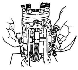
FIGURE 3-102. Installing Throttle Shaft Assembly (Typical)
bk.
Slide damper barrel assembly (41, FIGURE 3-64) over damper piston (43) and slide throttle shaft assembly
(18) through damper barrel (41), throttle shaft spacer (20), and throttle lever (19).
NOTE
Tighten low idle lock nut (40) 30 to 35 in-lbs (3.5 to 4 Nm).
3-118
|
|