ARMY TM 9-2815-256-24
AIR FORCE TO 38G1-96-2
MARINE CORPS TM 2815-24/5
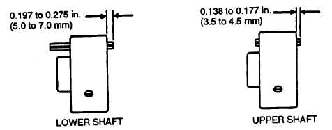
FIGURE 3-135. Spring Pin Protrusion
CAUTION
Upper and lower idler gear sleeve bearings (4 and 12, FIGURE 3-134) have the same ID, but are
different. Sleeve bearing with spiral oil groove goes in lower idler gear. Sleeve bearing without
groove goes in upper idler gear (pressure lubed). Do not intermix sleeve bearings or premature
sleeve bearing failure will result.
d.
If sleeve bearings (4 and 12) were removed, use an arbor press, driver (JD-252), and handle (10914188) to
install sleeve bearing (4) in idler gear (3) and sleeve bearing (12) in idler gear (11).
e.
Install lower idler gear (11), thrust washer (10), and nut (8).
f.
Time camshaft and install upper idler gear (3), thrust washer (2), and capscrew (1), refer to paragraph 3-40.3.
g.
Install oil pan, refer to paragraph 3-20.3.
h.
Install timing gear cover, refer to paragraph 3-39.3.
3-42. FRONT PLATE.
3-42.1. Removal.
a.
Remove timing gear cover, refer to paragraph 3-39.1.
b.
Remove camshaft, refer to paragraph 3-40.1.
c.
Remove fuel injection pump and drive gear, refer to paragraph 3-27.1.
d.
Remove oil pump and drive gear, refer to paragraph 3-21.1.
e.
Remove idler gears, refer to paragraph 3-41.1.
f.
Remove five screws (1, FIGURE 3-136) and lockwashers (2) securing front plate (3); remove front plate (3) and
gasket (4). Discard gasket (4) and lockwashers (2).
g.
Remove oil bypass valve (6) and spring (5).
h.
If new front plate (3) is to be installed, remove setscrew plugs (7). Discard plugs.
Change 3
3-176
|
|