ARMY TM 9-2815-259-24
AIR FORCE TO 38G1-125-2
MARINE CORPS 09249A/09246A-24
5-116
5
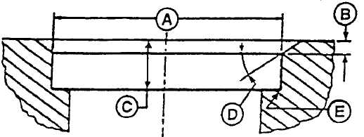
Measure intake and exhaust valve seat bore in cylinder head, refer to Figure 5-94
for measurement locations. If bore dimensions are not within specifications
shown in Table 5-12, machine cylinder head to specifications or replace cylinder
head.
FIGURE 5-94. MEASURE VALVE SEAT BORE IN CYLINDER HEAD
6
Install valve seat inserts in cylinder head using pilot driver and valve seat insert
installing adapter. Use one end of valve seat insert installing adapter to install
intake valve seat inserts, the other end is used to install exhaust valve seat
inserts.
7
Grind valve seats as required to maintain correct valve recess and valve face-to-
seat seal, refer to step 4 (l).
c. Assembly.
(1)
Lubricate stems of valves (10 and 11, Figure 4-52) and valve guides with clean engine oil.
NOTE
If valves are reused, install valves in same location from which removed.
(2)
Insert valves (10 and 11) in cylinder head.
(3)
Use valve stem seal installer to slide valve stem seals (13) over stems of valves (10 and 11) and
onto valve guide tower (3, Figure 5-95).
(4)
Position valve springs (4, Figure 4-52) and rotators (3) on cylinder head.
(5)
Compress valve springs (4, Figure 4-52) using valve spring compressor (JDE138) and install
retainers on stems of valves (10 and 11).
(6)
Strike end of each valve three or four times using soft, non-metallic mallet to insure proper
positioning of retainer locks.
|
|