ARMY TM 9-2815-260-24
AIR FORCE TO 38G1-126-2
MARINE CORPS TM 09244A/09245A-24
5-35
(36)
Orient pivot shaft (54) with knife edge facing transfer pump end of fuel injection pump housing.
Carefully install pivot shaft (54) into fuel injection pump housing and through openings in
governor arm (55).
(37)
Position O-ring seals (53) on pivot shaft (54) and install pivot shaft nuts (52) finger tight.
NOTE
Finish torque sequence with shaft nut on linkage hook side of pump.
(38)
Torque each pivot shaft nut (52) alternately to 20 to 25 lb-in. (2.3 to 2.8 Nm).
(39)
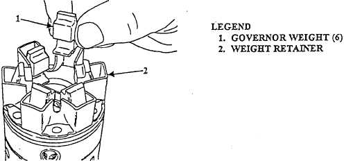
Invert head and rotor assembly and install governor weights (1, Figure 5-44) into weight retainer
(2) with rounded "heels" of governor weights in corners of weight retainer sockets.
FIGURE 5-44. GOVERNOR WEIGHT INSTALLATION (TYPICAL).
(40)
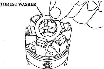
Install thrust washer (Figure 5-45) so that thrust washer is resting on top of governor weight
(1, Figure 5-44) "toes".
FIGURE 5-45. THRUST WASHER INSTALLATION (TYPICAL).
|
|