ARMY TM 9-2815-260-24
AIR FORCE TO 38G1-126-2
MARINE CORPS TM 09244A/09245A-24
5-37
(44)
Align drill point (2, Figure 5-47) in rotor with head locating screw bore at bottom of head. Align
cam pin hole in cam ring (88, Figure 5-1) with head locating screw bore in hydraulic head.
(45)
Orient governor thrust sleeve (1, Figure 5-46) so that governor arm groove is in horizontal
position.
(46)
Carefully slide head and rotor assembly into fuel injection pump housing with metering valve bore
(3) at the 12 o’clock position (straight up). When hydraulic head seal contacts fuel injection pump
housing, push head and rotor assembly in with slight twisting motion until head locking screw
bore in head and rotor assembly aligns with head locating screw bore in fuel injection pump
housing.
(47)
Install vent wire assembly (47, Figure 5-1) into hydraulic head until it bottoms. Ensure that vent
wire assembly does not protrude above surface of hydraulic head.
(48)
Install shim (45), spring (44), and metering valve arm (43).
NOTE
Rotate hydraulic head slightly counterclockwise to aid in installing linkage
hook onto pin on metering valve arm.
(49)
Engage linkage hook (56) to cutout in governor arm (43) and fit linkage hook onto pin on
metering valve arm (41).
(50)
Install head locking screws (23) finger tight.
(51)
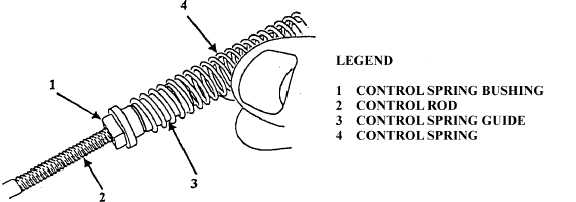
Thread control spring bushing (1, Figure 5-48) onto control rod (2) until control spring bushing
contacts control spring guide (3). Thread control spring (4) five full turns onto control spring
guide.
FIGURE 5-48. CONTROL SPRING INSTALLATION.
|
|