
| Tweet |

Custom Search
|
|

|
||
 TM 9-8000
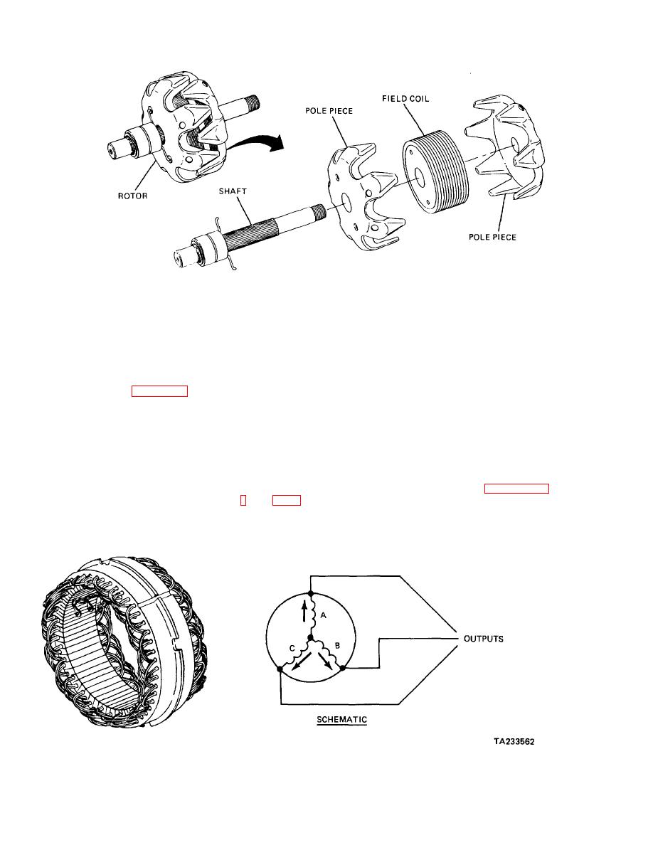
Figure 13-25. Rotor Construction.
field winding on the shaft. Each pole piece has finger -
The rotor is synchronized to the stator; that is, when one
like projections. When the rotor is assembled, the
north pole projection is aligned with one of the loops of
projections interlock with each other. The pole pieces
one-phase winding loop, the other north pole projections
form north and south magnetic poles. The core of the
will also align with the other loops of that phase winding.
rotor contains the axially wound field winding which is
This sequence of alignment between the rotor
made of varnish-insulated copper wire. Each end of the
projections is necessary for operation. If one-phase
field winding is connected to an individual slipring.
winding was being acted on by a negative pole projection
c. Stator Design (Fig. 13-26). The stator is' designed
at one loop and a positive pole projection at another
loop, the two loops would cancel each other out and no
with three separate windings so that it produces three
current would be generated.
separate ac currents. This is known as three-phase
output. Each winding is in the form of loops that are
spaced at intervals on the frame. The windings then are
13-24. Common Alternator Designs. The following
arranged so that they are offset from each other. The
are brief descriptions of various configurations of
three windings are all tied together at one end to form
alternators.
what is known as a wye wound stator.
d.
Rotor-to-Stator
Relationship
(Fig.
configuration of a typical wound- pole alternator with
rotating field. Alternate
Figure 13-26. Wound-Pole Alternator.
13-26
|
||
|
||


