
| Tweet |

Custom Search
|
|

|
||
 TM 9-8000
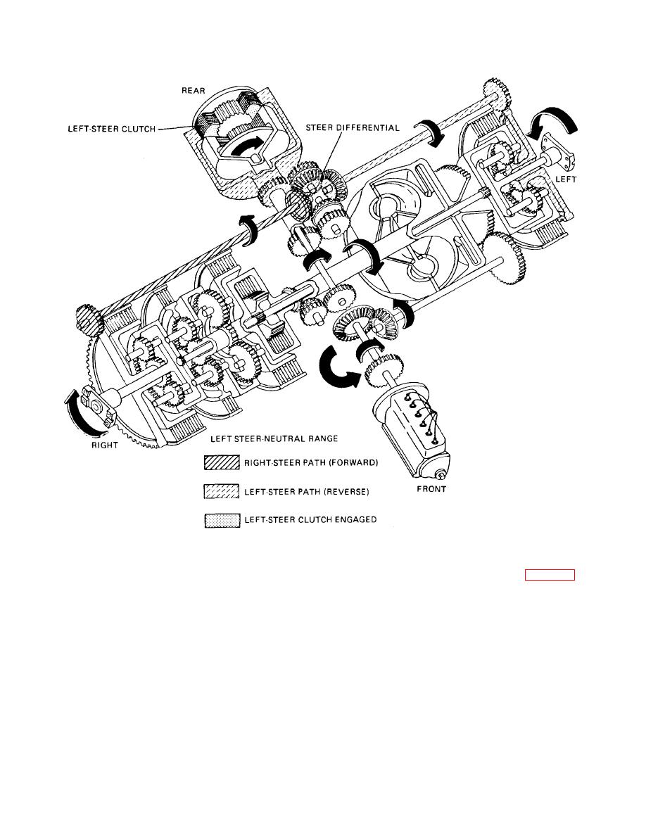
Figure 24-7. Power Flow through Cross Drive Transmission during Left Steering in Neutral Range (Part C)
various pressure regulating valves. Main pressure from
includes a friction disk brake assembly (fig. 24-11). Each
the oil pump is admitted to the valve body through line
assembly consists of six internally splined disks splined
(15). The main-pressure regulator valve (16) prevents
to the output planet carrier and five externally splined
excessive pressure while the main-pressure relief valve
disks splined to the brake anchor. The brake anchor is
(14) opens to permit excessive oil to flow back to the oil
bolted to the transmission end plate and, there- fore, is
reservoir. Oil pressure to the converter is regulated by
stationary. Inside the brake anchor is a brake-apply cam-
valve (6) while oil pressure to the lubrication system is
stationary ring. Next to the stationary ring is a brake-
regulated by valve (7). Valve (11) is a cooler bypass
apply cam-rotating ring. A single brake pedal in the
valve that bypasses oil from the lubrication system and is
driver's compartment applies both brakes at the same
not needed to maintain pressure. Valve (3) is a steering-
time. When a brake is applied, mechanical linkage
overspeed safety valve that prevents excessive pressure
causes the brake-apply shaft to rotate. This causes the
to the steer clutches that would result in rapid steering.
TA233734
24-8. Braking. Each of the two output planetary systems
24-13
|
||
|
||


