
| Tweet |

Custom Search
|
|

|
||
 TM 9-8000
and the plane in which the balls lie will be reduced to 80
remaining in a plane that bisects the angle between the
degrees, fulfilling the requirement that the balls must lie
two shafts. The fork ends subtend an angle greater than
In the plane that bisects the angle of drive.
180 degrees so as to be self-locking once the joint is
assembled to the inner parts of the joint. A flat surface is
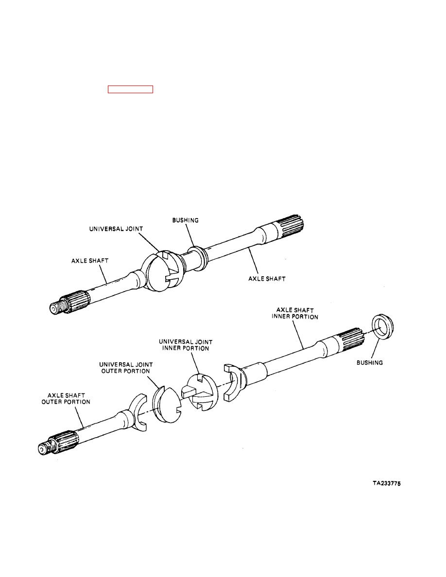
c. Tracta Joint (Fig.
milled on the cylindrical section of the joint to permit the
The
Tracta
Joint to be Inserted in place.
universal joint is the simplest to Install and service. It is,
in effect, one universal joint within another, with points of
d. Double Cross and Roller (Flg. 28-8). The
driving contact on the outer portions of the Joint. This
double cross and roller Joint uses two cross and roller
universal Joint consists of four main parts: a forked
Joints in tandem to form a single joint. The joints are
driving shaft, a forked driven shaft, a female (or slotted)
linked through a centering yoke that works In conjunction
Joint, and a male (or spigot) Joint. The complete Inner
with specially designed, spring-loaded centering ball.
Joint, consisting of the female Joint and the male Joint,
The components are contained within the center
floats between the forks; movement between the
coupling yoke. As the shaft rotates, the action of the
Individual halves of the Inner Joint is permitted In a
centering ball and yoke act to maintain an equally divided
direction perpendicular to that permitted by the slotted
drive angle between the connected shafts, resulting In a
forks, by the action of the spigot moving In the slot. With
constant drive velocity.
this arrangement, the points of driving contact are
allowed to move as the universal joint rotates, thereby
Figure 28-7. Tracta Constant Velocity Joint.
28-8
|
||
|
||


