
| Tweet |

Custom Search
|
|

|
||
 3500 ENGINE
SPECIFICATIONS
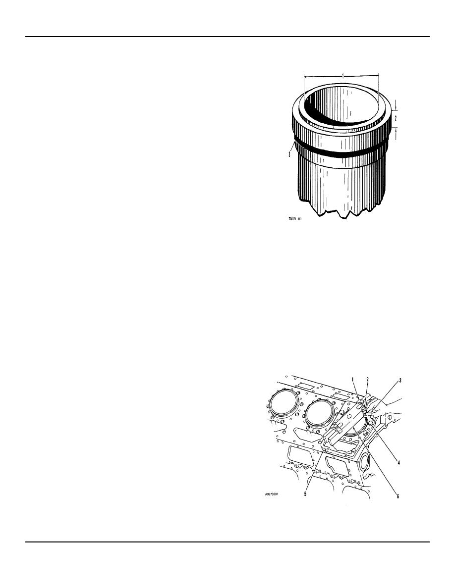
CYLINDER LINERS
For Installation
a. Put liquid soap on cylinder block liner bore
surfaces and rubber seals on the lower part
of the liner.
b.
Put the filler band completely in clean
engine oil for a moment.
c.
Install filler band (3) in the groove under the
liner flange, without delay.
d.
Install the liner in the bore immediately,
before expansion of the filler band.
(1)
Bore in liner
(new)....................... 170.0250.025
mm
(6
6939 0010 in.)
(2)
Thickness of flange
on liner............ 12.65 0.02 mm (.498 001 in )
(3)
Filler Band.
CYLINDER LINER PROJECTION
liner must be.......................... 0.059 to 0
199 mm (.0023 to .0078 in.)
Make reference to CYLINDER LINER PROJECTION in
Testing and Adjusting for the complete procedure.
Maximum permissible difference between
all four measurements .......... 0.05
mm
1.
Install the gasket and spacer plate (5).
(.002 in.)
Install copper washers and bolts (4) to hold
the spacer plate Tighten bolts (4) evenly in
(1)
3H465 Plate
four steps.
1st step .................. 14 Nm (10 lb. ft.)
(6)
8B7548 Push-Puller Crossbar.
2nd step ................. 35 Nm (25 lb. ft )
3rd step................... 70 Nm (50 lb. ft )
4th step ................... 95 Nm (70 lb. ft )
2.
Install tooling as shown. Tighten bolts for
crossbar evenly in four steps.
1st step .....................
7 Nm (5 lb ft.)
2nd step .......................
20 Nm (15 lb ft )
3rd step.......................... 35 Nm (25 lb ft.)
4th step ........................ 70 Nm (50 lb ft.)
3. Measure cylinder liner projection with dial
indicator (2) in 1P2402 Gauge Body (3) as
shown Measure at four places around each
cylinder liner near the clamped area
Average of four projection measurements
from
any
cylinder
NOTE: FOR TORQUE VALUES NOT GIVEN, SEE THE FIRST35 PAGE OF SPECIFICATIONS FOR
GENERAL TIGHTENING TORQUES
35
|
||
|
||


