
| Tweet |

Custom Search
|
|

|
||
 FUEL SYSTEM
SYSTEMS OPERATION
Governor accumulator oil pressure is changed to
a restricted variable (pulsating) oil flow as small holes
(ports) in the pilot valve bushing move past a passage in
the controlet housing. In a constant speed opera- tion,
the ball valve is not tight against its seat and lets oil flow
back to the sump. The ball valve is held in position by
the sensing bellows, which is connected to inlet manifold
air pressure. The force used to hold the ball valve is
proportional to the inlet manifold air pressure.
As inlet manifold air pressure increases, the ball
valve makes contact with its seat and oil pressure
increases to move the limiter piston to the right against
the force of the restoring spring. This movement
increases the tension on the restoring spring until the
spring force is in balance with the sensing bellows force.
The oil pressure now can push the ball valve off its seat
and let a small amount of oil flow to the sump. This
reduces the pressure behind the limiter piston and the
piston stops movement.
The piston position is
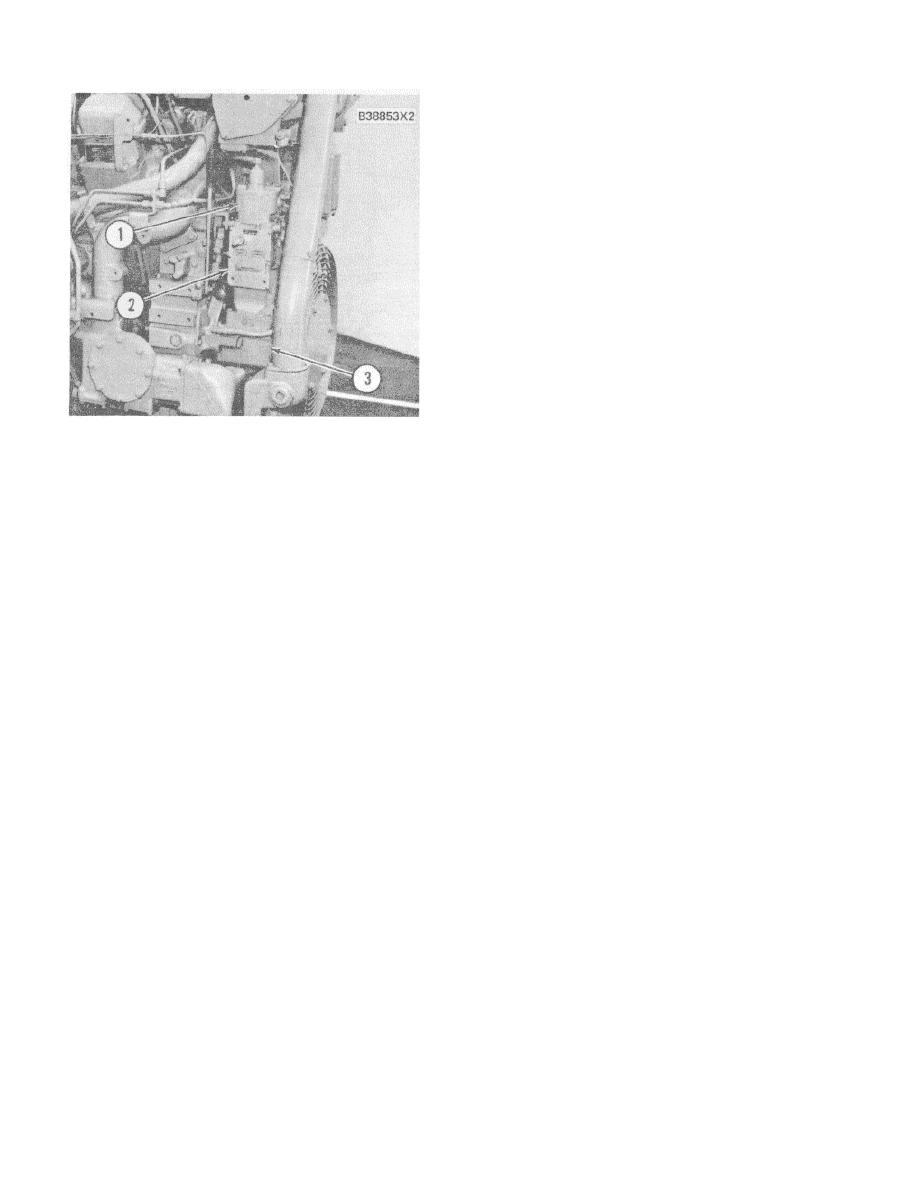
UG8 LEVER GOVERNOR
proportional to inlet manifold air pressure.
1. Air-Fuel ratio control. 2. Governor. 3. Governor
drive.
The cam fastened to the limiter piston operates
AIR FUEL RATIO CONTROL
through linkage to limit the travel of the governor terminal
shaft. The governor terminal shaft limits the fuel to the
The air fuel ratio control is installed on top of the basic
engine through the fuel control link- age. The terminal
UG8L Governor. The unit is made up of an inlet
shaft can turn in the increase fuel direction until the pivot
manifold pressure sensor, a hydraulic circuit and
lever lifts the pilot valve above center. Oil pressure on
mechanical linkage that connects the unit to the
the bottom of the power piston is now directed to the
governor. Pressure oil from the governor hydraulic
sump. The power piston moves down and causes the
system is used to operate the unit.
terminal shaft to turn in the decrease fuel direction.
When engine speed or load is increased rapidly, it is
When the engine is stopped, the limiter piston is
possible for a standard (unlimited) governor to supply
held to the left by the restoring spring. The fuel limit
more fuel than can be burned with the amount of
valve at this position is set high enough by the cam to
available air. Too much smoke and poor acceleration
give enough fuel for start up. At cranking speed, oil
are the result. The fuel ratio control works to limit the
pressure behind the limiter piston goes by the diaphram
movement of the governor terminal shaft in the increase
to the sump. After the engine has started, engine
fuel direction as a direct result of inlet manifold pressure.
lubrication oil pressure pushes the diaphram against its
Thus, fuel which can be burned is limited to the air
seat and closes the governor oil drain. Oil pressure now
available for combustion as the engine speed is
increases behind the limiter piston. The limiter piston
increased. This gives more complete combustion and
moves out until the roller follower is on the operating
keeps smoke to a minimum while acceleration is
slope of the cam. At this point the ball valve is moved off
improved.
its seat, the oil can now flow to sump and the piston
movement is stopped.
The air fuel ratio is also used for protection to limit the
fuel as the result of any large, sudden restriction of air
supply to the engine.
73
|
||
|
||


