
| Tweet |

Custom Search
|
|

|
||
 FUEL SYSTEM
TESTING AND ADJUSTING
ENGINE ROTATION
SAE standard engine crankshaft rotation is
counterclockwise as seen from the flywheel end of the
engine.
FINDING TOP CENTER POSITION FOR NO. 1
PISTON
Tools Needed:
9S9082 Engine Turning Tool.
TIMING BOLT INSTALLATION
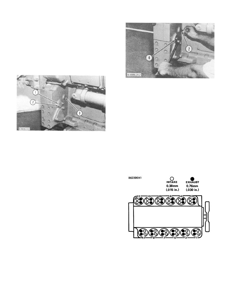
2. Timing bolt. 4. 9S9082 Engine Turning Tool.
4.
The intake and exhaust valves for the No. 1
cylinder are fully closed if No. 1 piston is on the
compression stroke and the rocker arms can be
moved by hand. If the rocker arms can not be
moved and the valves are slightly open, the No.
1 piston is on the exhaust stroke.
Make
reference to charts for CRANKSHAFT
POSITIONS FOR INJECTOR TIMING AND
VALVE CLEARANCE SETTING to find the
correct cylinder(s) to be checked/adjusted for the
TIMING BOLT LOCATION
stroke position of the crankshaft when the timing
1. Cover. 2. Timing bolt. 3. Timing bolt hole In
bolt has been installed in the flywheel.
flywheel housing.
NOTE: When the actual stroke position is identified, and
1.
Remove cover (1) and the timing hole plug from
the other stroke position is needed, it is necessary to
the right front side of the flywheel housing. On
remove the timing bolt from the flywheel and turn the
some engines there is a cover and timing bolt
flywheel 3600 in the direction of normal engine rotation.
hole located on the left side, also.
2.
Put timing bolt (2) [long bolt that holds cover (1)
on the flywheel housing] through the timing hole
in the flywheel housing. Use the 9S9082 Engine
Turning Tool (4) and 1/2" drive ratchet wrench to
turn the engine flywheel in the direction of
normal engine rotation until the timing bolt
engages with the threaded hole in the flywheel.
NOTE: If the flywheel is turned beyond the point that the
timing bolt engages in the threaded hole, the flywheel
must be turned opposite normal engine rotation
approximately 30 degrees. Then turn the flywheel in the
direction of normal engine rotation until the timing bolt
engages with the threaded hole. The reason for this
procedure is to make sure the play is removed from the
gears when the No. 1 piston is put on top center.
CYLINDER AND VALVE LOCATION
(3512 SHOWN)
3.
Remove the valve cover for the No. I cylinder
head.
117
|
||
|
||


