
| Tweet |

Custom Search
|
|

|
||
 BASIC BLOCK
TESTING AND ADJUSTING
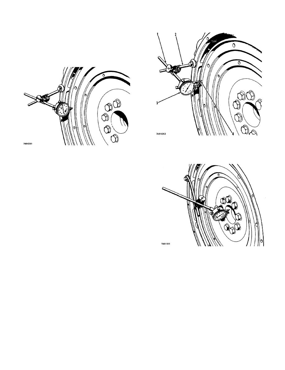
Face Runout (axial eccentricity) of the Flywheel
1.
Install the dial indicator as shown. Always put a
force on the crankshaft in the same direction
before the indicator is read so the crankshaft
end clearance (movement) is always removed.
CHECKING BORE RUNOUT OF THE FLYWHEEL
1. 7H1945 Holding Rod. 2. 7H1645 Holding Rod. 3.
7H1942 Indicator. 4. 7H1940 Universal Attachment.
CHECKING FACE RUNOUT OF THE FLYWHEEL
2.
Set the dial indicator to read "0" (zero).
3.
Turn the flywheel and read the indicator every
90.
4.
The difference between the lower and higher
measurements taken at all four points must not
be more than 0.15 mm (.006 in.), which is the
maximum permissible face runout (axial
eccentricity) of the flywheel.
Bore Runout (radial eccentricity) of the Flywheel
1.
Install the dial indicator (3) and make an
adjustment of the universal attachment (4) so it
makes contact as shown.
2.
Set the dial indicator to read "0" (zero).
CHECKING FLYWHEEL CLUTCH PILOT BEARING
BORE
3.
Turn the flywheel and read the indicator every
90.
CHECKING CRANKSHAFT DEFLECTION (BEND)
4.
The difference between the lower and higher
The crankshaft can be deflected (bent) because
measurements taken at all four points must not
the installation of the engine was not correct. If the
be more than 0.15 mm (.006 in.), which is the
engine mounting rails are not fastened correctly to the
maximum permissible bore runout (radial
foundation mounting rails, the cylinder block can twist or
eccentricity) of the flywheel.
bend and cause the crankshaft to deflect.
This
deflection can cause crankshaft and bearing failure.
5.
Runout (eccentricity) of the bore for the pilot
bearing for the flywheel clutch, must not exceed
0.13 mm (.005 in.).
148
|
||
|
||


