
| Tweet |

Custom Search
|
|

|
||
 BASIC BLOCK
TESTING AND ADJUSTING
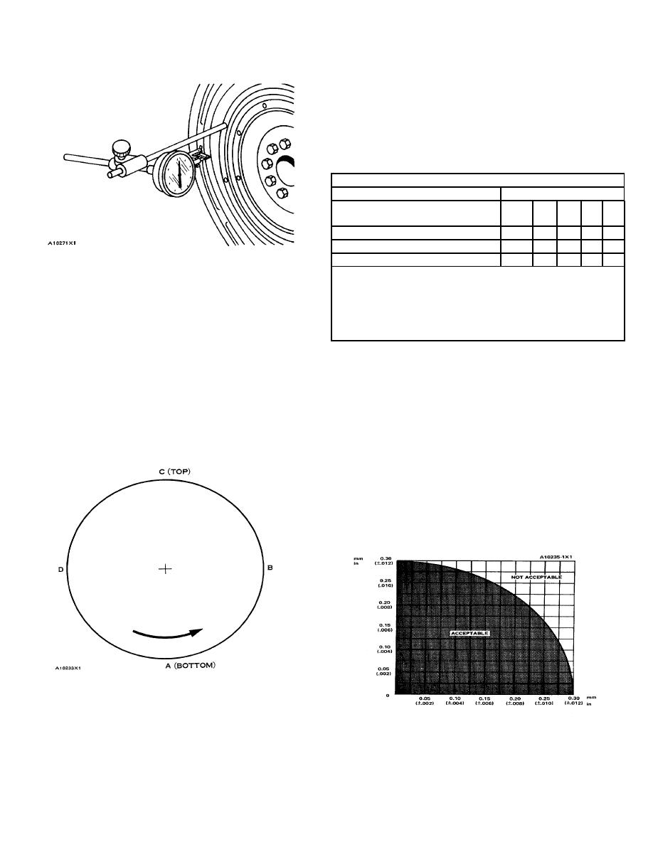
6.
Turn the crankshaft counterclockwise to put the
dial indicator at (C). Write the measurement in
the chart.
7.
Turn the crankshaft counterclockwise to put the
dial indicator at (D). Write the measurement in
the chart.
CHART FOR DIAL INDICATOR MEASUREMENTS
Position of dial indicator
Line
No.
A
BCD
Correction for bearing clearance
I
0
Dial Indicator Reading
II
0
Total of Line 1 & 2
III
0
8S2328 DIAL INDICATOR GROUP INSTALLED
*Total Vertical eccentricity (out of round).
NOTE: Write the dial indicator measurements with
**Subtract the smaller No. from the larger No.
The
difference is the total horizontal eccentricity.
their positive (+) and negative (-) notation (signs).
This notation is necessary for making the
A10234X5
calculations in the chart correctly.
8.
Add lines I & II by columns.
3.
Divide the measurement from Step 2 by 2. Write
this number on line 1 in columns (B) & (D).
9.
Subtract the smaller number from the larger
number in line III in columns (B) & (D). The
4.
Turn the crankshaft to put the dial indicator at
result is the horizontal eccentricity (out of round).
(A). Adjust the dial indicator to "O" (zero).
Line III, column (C) is the vertical eccentricity.
5.
Turn the crankshaft counterclockwise to put the
10.
On the graph for total eccentricity, find the point
dial indicator at (B). Write the measurements in
of intersection of the lines for vertical eccentricity
the chart.
and horizontal eccentricity.
11.
If the point of intersection is in the range marked
"Acceptable", the bore is in alignment. If the
point of intersection is in the range marked "Not
Acceptable", the flywheel housing must be
changed.
CHECKING BORE RUNOUT OF THE FLYWHEEL
HOUSING
GRAPH FOR TOTAL ECCENTRICITY
147
|
||
|
||


