
| Tweet |

Custom Search
|
|

|
||
 BASIC BLOCK
TESTING AND ADJUSTING
c.
Check the distance from the bottom edge of
1.
Fasten a dial indicator to the crankshaft flange
crossbar (6) to the top edge of the spacer
so the anvil of the indicator will touch the face of the
plate. The distance on each end of the
flywheel housing.
crossbar must be the same.
2.
Put a force on the crankshaft toward the rear
5.
Use 8T455 Liner Projection Tool Group to
before the indicator is read at each point.
measure liner projection.
6.
To zero dial indicator (2), use the back of 1
P5507 Gauge with dial indicator (2) mounted in
1P2402 Gauge Body (3).
7.
Liner projection must be 0.059 to 0.199 mm
(.0023 to .0078 in.). Make the measurement to
the outer flange of the liner, not the inner ring.
The maximum difference between high and low
measurements made at four places around each
liner is 0.05 mm (.002 in.).
NOTE: If liner projection changes from point to point
around the liner, turn the liner to a new position within the
bore. If still not within specifications, move liner to a
different bore.
NOTE: When liner projection is correct, put a temporary
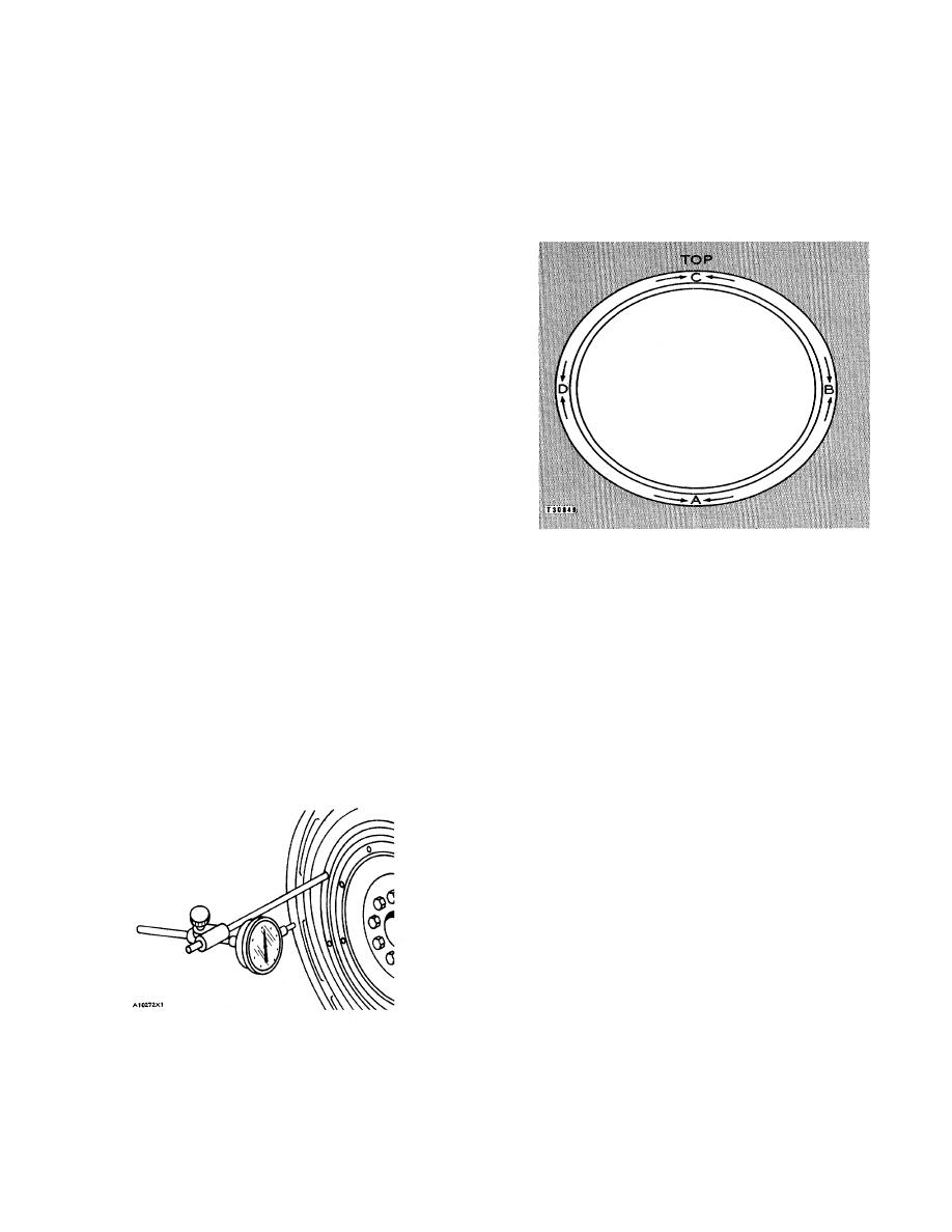
CHECKING FACE RUNOUT OF THE FLYWHEEL
mark on the liner and spacer plate so when the seals
HOUSING
and band are installed, the liner can be installed in the
A. Bottom. B. Right side. C. Top. D. Left side.
correct position.
3.
With dial indicator set at "O" (zero) at location
(A), turn the crankshaft and read the indicator at
FLYWHEEL AND FLYWHEEL HOUSING
locations (B), (C) and (D).
Tools Needed:
4.
The difference between lower and higher
8S2328 Dial Indicator Group.
measurements taken at all four points must not
be more than 0.30 mm (.012 in.), which is the
Face Run Out (axial eccentricity) of the Flywheel
maximum permissible face run out (axial
Housing
eccentricity) of the flywheel housing.
Bore Runout (radial eccentricity) of the Flywheel
Housing
1.
Fasten the dial indicator as shown so the anvil of
the indicator will touch the bore of the flywheel
housing.
2.
With the dial indicator in position at (C), adjust
the dial indicator to "O" (zero).
Push the
crankshaft up against the top of the bearing.
Write the measurement for bearing clearance on
line 1 in column (C) in the CHART FOR DIAL
INDICATOR MEASUREMENTS.
8S2328 DIAL INDICATOR GROUP INSTALLED
146
|
||
|
||


