
| Tweet |

Custom Search
|
|

|
||
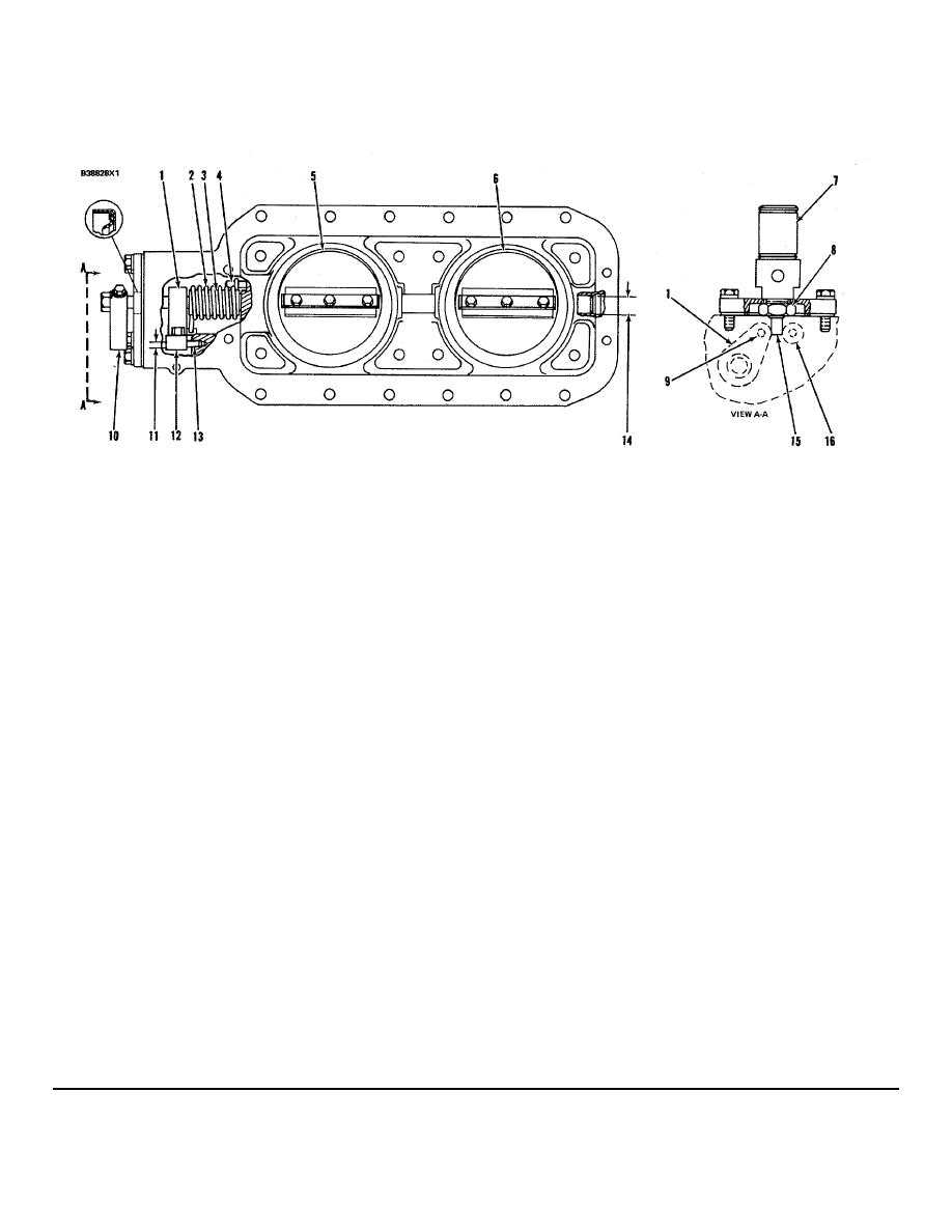 HYDRAMECHANICAL PROTECTIVE SYSTEM
SPECIFICATIONS
AIR INTAKE SHUTOFF
(5N9060)
(1)
Install shaft assembly in housing as follows:
shutoff group in the "open" position and install the
a. Install spacer (3) and spring (2) on shaft
gasket, flange and cylinder with cylinder shaft (15)
assembly (1).
between the spacer assembly in the shaft lever and
b. Install the assembly in the housing. Turn
spacer assembly (16). The bolts that hold the unit to
spring (2) until it engages correctly with pin
the aftercooler housing can now be installed.
(4).
c. Install handle (10) on the shaft assembly
(8)
Torque for nut that holds cylinder to
flange .............................. 457 Nm (335 lb. ft.)
(1). Turn shaft assembly (1) upward and
install pin (13) so handle (10) can rest on
(9)
Diameter of
pin ...............6.299 + 0.008 mm (.2480.0003 in.)
pin (13).
d. With the shaft assembly and handle (10) in
Bore in spacer bushing for pin (after
contact with pin (13), install plate
assembly)......6.3140.011 mm (.2486.0004 in.)
assemblies (5) and (6) on the shaft
Bore in spacer for
assembly.
bushing..........7.9380.013 mm (.3125.0005 in.)
e. Remove pin (13) to release the handle and
(10)
Handle.
let plate assemblies (5) and (6) move to the
(11)
Diameter of
"shutoff" position. A 0.08 mm (.003 in.)
pin (13) ..........6.2990.008 mm (.2480.0003 in.)
feeler gauge should not pass between each
Bore in housing for
plate assembly and the housing.
pin .................6.4080.051 mm (.2523.0020 in.)
f.
Remove handle (10) and install spacer
Bore in spacer bushing for pin (after
assembly (12), pin (13), the gasket, cover
assembly)......6.3140.011 mm (.2486.0004 in.)
assembly and handle(10).
Bore in spacer for
(2)
Spring.
bushing..........7.9380.013 mm (.3125.0005 in.)
(3)
Spacer for spring (2):
Bore in spacer for
(12)
Spacer.
shaft......................... 20.800.25 mm (.819.010 in.)
(13)
Pin.
Diameter of shaft.18.940.02 mm (.746.001 in.)
Diameter of shaft .. 18.94 40.02 mm (.746.001 in.)
(14)
Inside diameter of bushings for
(4)
Pin.
shaft ............19.0500.044 mm (.7500.0017 in.)
(5)
Plate assembly.
(6)
Plate assembly.
(15)
Hydraulic cylinder shaft
(7)
Hydraulic cylinder must be installed before the air
(16)
Spacer assembly.
shutoff can be installed on the engine. Put the air
NOTE: FOR TORQUE VALUES NOT GIVEN, SEE THE FIRST
PAGE OF SPECIFICATIONS FOR GENERAL TIGHTENING TORQUES
206
|
||
|
||


