
| Tweet |

Custom Search
|
|

|
||
 3500 ENGINES
DISASSEMBLY AND ASSEMBLY
FUEL INJECTION CONTROL LINKAGE
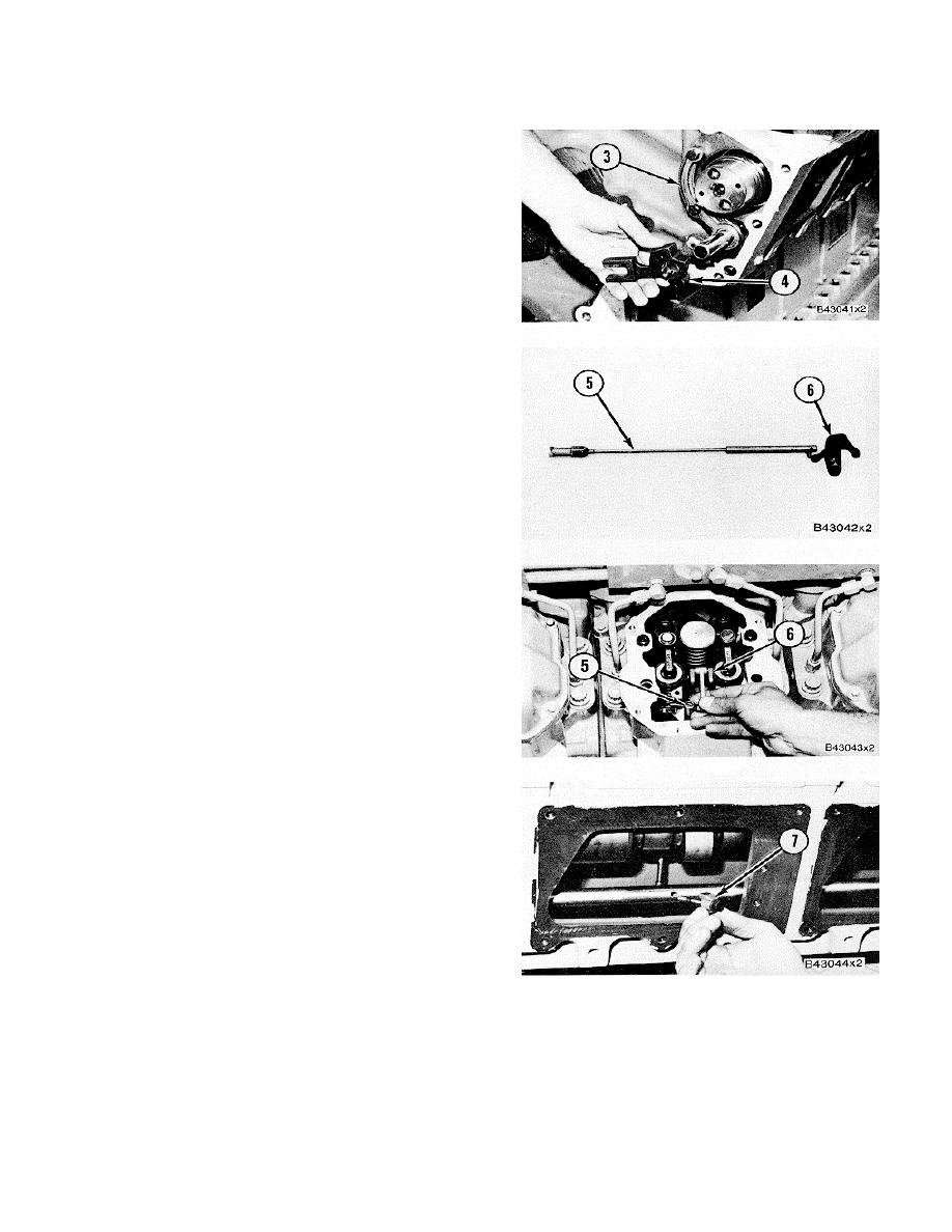
5.
Install supports (3) to hold the front of the control
shafts. Install levers (4) on each of the control
shafts.
6.
Connect lever assembly (6) to rod assembly (5).
7.
Install lever assembly (6) and rod assembly (5)
as a unit in each cylinder head. If necessary,
use tool (B) to turn the engine flywheel until the
camshaft moves enough to permit the lever of
the rod assembly to move into position.
8.
Make sure lever assembly (6) is engaged
correctly with the fuel injection pump rack and
install the two bolts to hold it in place.
9.
Make sure the lever for the fuel control and
assembly is in position on the control shaft and
install the bolt and cap (7).
375
|
||
|
||


