
| Tweet |

Custom Search
|
|

|
||
 3500 ENGINES
DISASSEMBLY AND ASSEMBLY
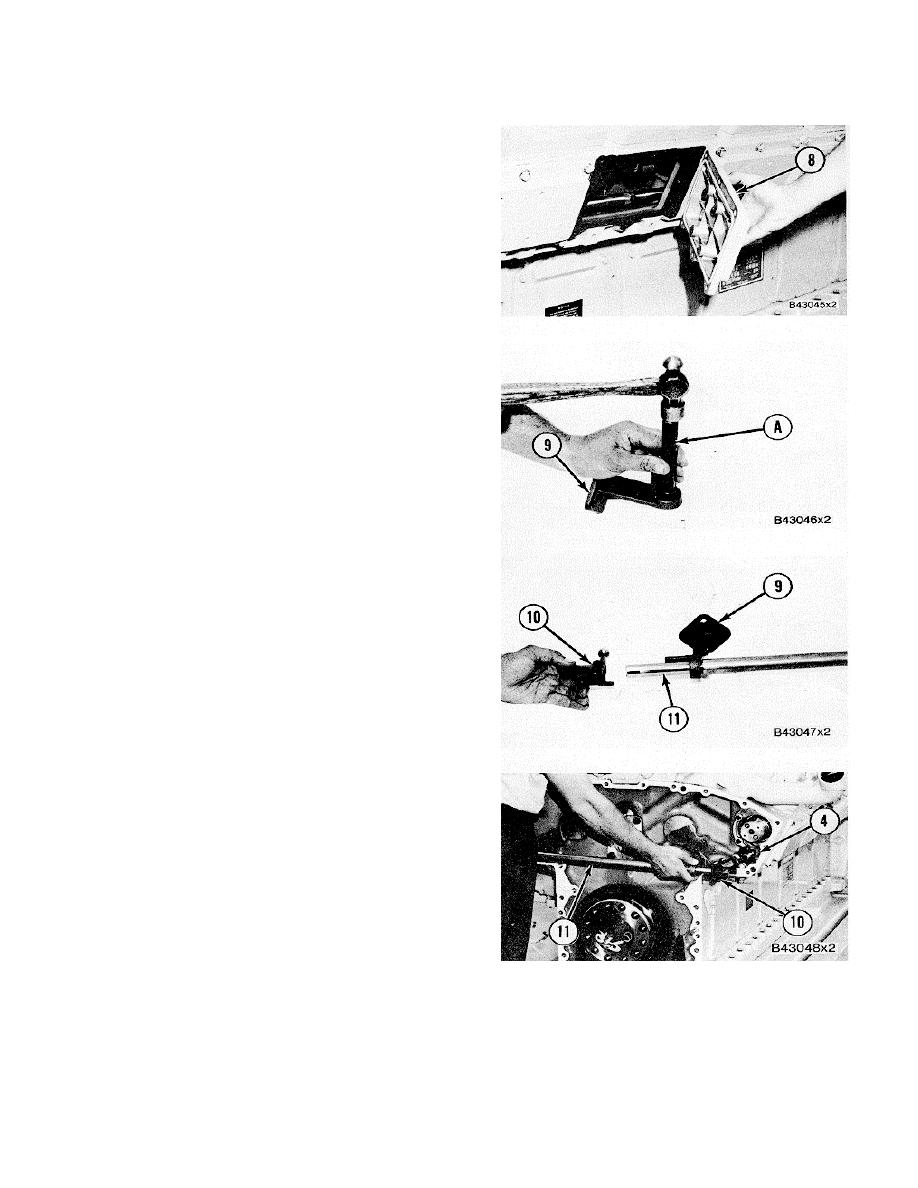
FUEL INJECTION CONTROL LINKAGE
10.
Install access covers (8) and seal over the
camshafts and control rods.
11.
Use tool group (A) and install the bearings in
the center of the bores in front control shaft
brackets (9). Check the bore in the bearings
after assembly. The bearing bores must be
21.925 + 0.015 mm (.8632 .0006 in.). If
necessary, make a replacement of the pins in
brackets (12). The pins must extend 8.0 + 0.5
mm (.315 .020 in.) above the surface of
brackets (9).
12.
Install brackets (9) and levers (10) on the ends
of front control shaft (11).
13.
Put shaft (11) in position on the front of the
engine. Make sure levers (10) and (4) are
engaged correctly and install the bolts to hold the
brackets and shaft (11 ) to the engine.
NOTE:
After assembly the control shafts must turn
freely by hand and the linkage must return to the
"SHUTOFF" position when it is turned and released.
See TESTING AND ADJUSTING section for the correct
adjustment of the fuel injection control group.
end by:
a) rocker shafts and push rods
b)
front drive housing
376
|
||
|
||


