| Tweet |

Custom Search
|
|

|
||
 3500 ENGINES
DISASSEMBLY AND ASSEMBLY
CAMSHAFTS
12.
Install the tachometer drive adapter on the other
camshaft to hold the drive gear in position. See
INSTALL TACHOMETER DRIVE.
13.
Remove the timing pins for the camshaft and
install the pins in their storage positions.
14.
Remove the timing bolt from the flywheel and
install the plug in the timing hole in the housing.
Remove tool (B) and install the cover on the
housing.
15.
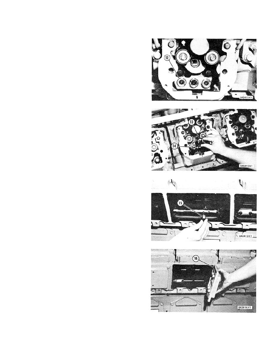
Remove the O-ring seals from valve lifters (12)
and push the lifters down against the camshaft.
16.
Install fuel rod assembly (14) and lever assembly
(13) as a unit in the cylinder heads. If necessary
use tool (B) to turn the flywheel until camshafts
move enough to permit the fuel rod assembly to
move into position.
17.
Make sure lever assembly (13) is engaged
correctly with the fuel injection pump rack and
install the bolts.
18.
Install the bolt and cap (15) to hold the fuel rod
assembly to the fuel control shaft.
19.
Install access covers (16) on each side of the
engine.
20.
See TESTING AND ADJUSTING section for the
correct adjustment of the fuel injection control
group.
end by:
a) install rocker shafts and push rods
b) install crankcase breather
c) install hydramechanical shutoff drive
d) install governor
405
|
||
 |
||