
| Tweet |

Custom Search
|
|

|
||
 3500 ENGINE ATTACHMENTS
SPECIFICATIONS
GOVERNOR FASTENER GROUP
(2301 Governors With EG10P Actuators)
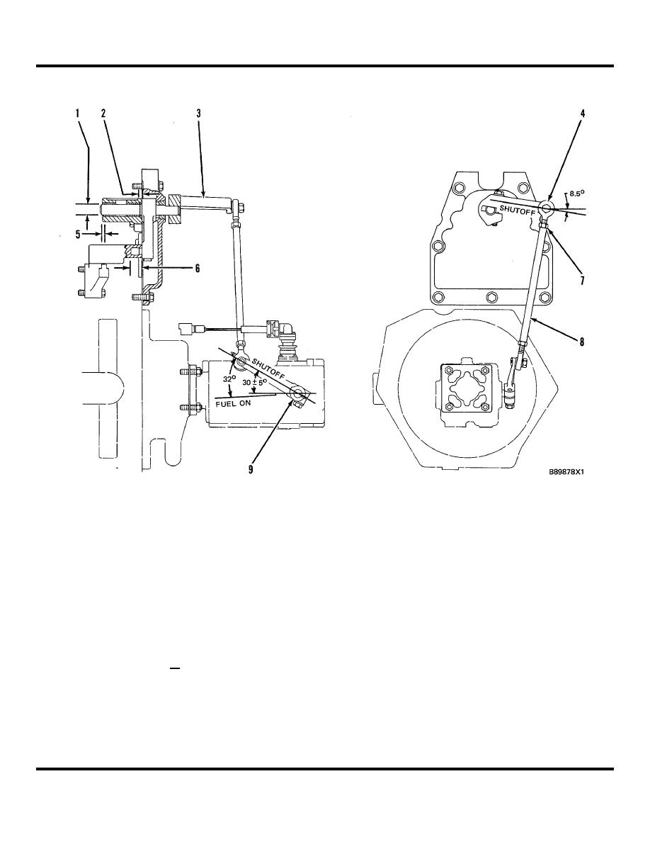
4W5030 Fastener Group
(1)
Diameter of shaft on lever
(8)
Rod assembly.
assembly .................................... 19.050 + 0.013
(9)
Lever.
mm (.7500 +
.0005 in.)
Linkage Adjustment:
Bore in bearings after assembly
1.
With control linkage in the SHUTOFF position
in bracket ................................... 19.126 _ 0.038
against its stop, install lever (3) as shown.
mm (.7530 +
2.
With actuator shaft in the SHUTOFF position
.0015 in.)
against its stop, lever (9) must be installed at
(2)
Distance bearing is installed from
the angle shown.
end of bracket 4.0 _+ 0.5 mm (.16 + .02 in.)
3.
With levers (3) and (9) in the SHUTOFF position,
(3)
Lever.
adjust rod end(4) and rod assembly (8) to the
(4)
Rod end.
needed length. Tighten nuts (7) to hold rod ends
(5)
Distance bearing is installed from
in position.
end of bracket 0.5 + 0.5 mm (.02 + .02 in.)
NOTE: Threads of rod ends (4) must be visible through
(6)
Distance pin is installed from
holes in rod to make sure there is minimum thread
lever ........................................... 181 mm (.71 +
engagement. Fill holes in rod with 9S3263 Thread Lock
.04 in.)
after adjustment is correct.
(7)
Nut: Tighten on each end of
rod assembly to a torque
4.
Connect levers (3) and (9) together with rod
of ............................................... 12 + 4 N-m (9 +
assembly (8).
3 lb. ft.)
418
|
||
|
||


