| Tweet |

Custom Search
|
|

|
||
 3500 ENGINE ATTACHMENTS
SPECIFICATIONS
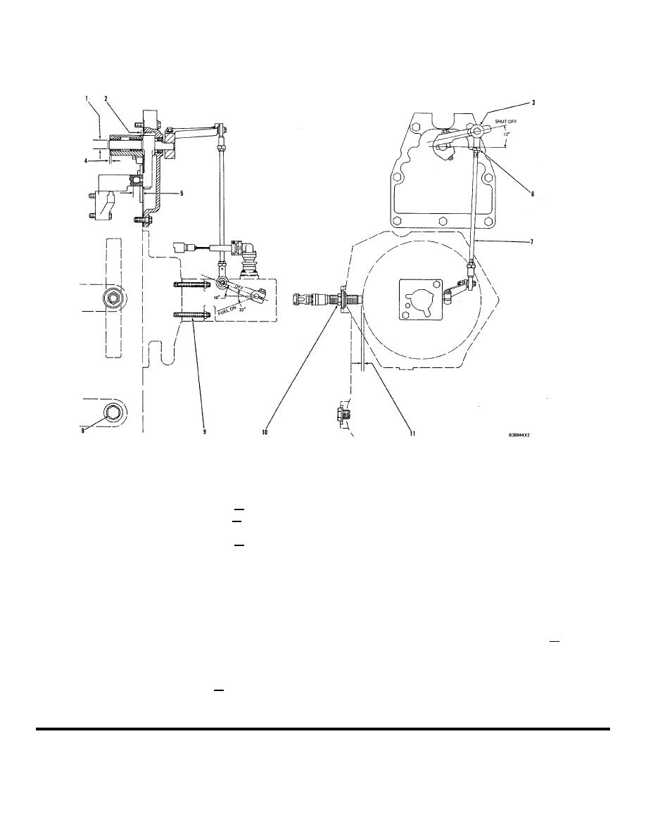
GOVERNOR FASTENER GROUP
(2301 Governor with EG3P Actuators)
8N116 Fastener Group
(6)
Tighten nut to a torque
(1)
Diameter of shaft on lever
of ............................................... 3.4 + 0.5 N-m
assembly .......................... 19.050 + 0.013 mm
(2.3 + .4 lb. ft.)
(.7500 + .0005 in.)
(7)
Rod assembly.
Bore in bearings after assembly
(8)
Tighten the plug to a torque
in bracket .......................... 19.126 + 0.038 mm
of ................................................ 70 15 N-m
(.7530 .0015 in.)
(50 + 11 lb. ft.)
(2)
Distance bearing is installed from
(9)
Tighten the studs in the bearing adapter to
end of bracket................... 4.0 + 0.5 mm (.16 +
a torque of ............................................... 15 + 5 N-m (11
.02 in.)
+ 4 lb. ft.)
(3)
Rod end. Adjust rod end (3) on rod assembly (7)
(10)
Tighten nut to a torque
to put the levers in the shut off position as
of ................................................ 68 + 13 N-m
shown.
(50 + 10 lb. ft.)
(4)
Distance bearing is installed from end of bracket
(11)
Distance between end of magnetic pick-up
.......................................... 0.5 + 0.5 mm (.02
and gear ..................................... 0.50 to .075
.02 in.)
mm (.020 to
(5)
Distance pin is installed from lever
.030 in.)
.......................................... 18 + 1 mm (.71 + .04
in.)
NOTE: FOR TORQUE VALUES NOT GIVEN, SEE THE FIRST
PAGE OF SPECIFICATIONS FOR GENERAL TIGHTENING TORQUES
417
|
||
 |
||