
| Tweet |

Custom Search
|
|

|
||
 3500 ENGINE ATTACHMENTS
SPECIFICATIONS
AIR INTAKE SHUTOFF
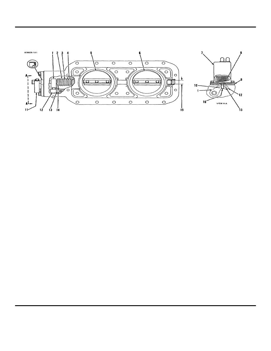
(5N9060)
(1)
Shaft assembly. Install in housing as follows:
(b) Turn air shutoff handle (11) to the "open"
a. Install spacer (3) and spring (2) on shaft
position and put plunger in position so the
assembly (1).
stop is between spacer assemble (12) and
b. Install the assembly in the housing. Turn
shaft assembly (1). Now release handle
spring (2) until it engages correctly with pin
(11) to allow shaft assembly to rest against
(4).
stop (16).
c. Temporarily install handle (11) on the shaft
(c) Install the lower gasket, spacer plate (9)
assembly (1). Turn shaft assembly (1)
and the upper gasket.
upward and install pin (13) a small distance
(d) Install spring (8) over plunger and install the
in bore (14) so handle (11) can rest on pin
solenoid assembly.
(13).
(8)
Spring.
d. With the shaft assembly and handle (11) in
(9)
Spacer plate.
contact with pin (13), install plate
(10)Diameter of
pin ........... 6.299 0.008 mm (.2480 .0003 in.)
assemblies (5) and (6) on the shaft
assembly.
Bore in spacer bushing for pin (after as-
e. Remove pin (13) to release the handle and
sembly)..... 6.314 0.011 mm (.2486 .0004 in.)
let plate assemblies (5) and (6) move to the
Bore in spacer for bush-
ing ........... 7.938 0.013 mm (.3125 .0005 in.)
"shutoff" position. A 0.08 mm (.003 in.)
feeler gauge should not pass between each
(11)Handle.
plate assembly and the housing.
(12)Spacer assembly.
f.
Remove handle (11) and install pin (13),
(13)Pin.
spacer assembly (12), the gasket, cover
(14)Diameter of
assembly and handle (11).
pin (13) ..... 6.299 0.008 mm (.2480 .0003 in.)
(2)
Spring.
Bore in housing for
(3)
Spacer for spring (2):
pin ........... 6.408 0.051 mm (.2523 .0020 in.)
Bore in spacer for
Bore in spacer assembly bushing for pin (after
shaft.............. 20.80 0.25 mm (.819 + .010 in.)
assembly)... 6.314 0.011 mm (.2486 .0004 in.)
Diameter of
Bore in spacer for
shaft................ 18.94 0.02 mm (.746 .001 in.)
bushing..... 7.938 0.013 mm (.3125 .0005 in.)
(4)
Pin.
(15)Diameter of
(5)
Plate assembly.
shaft .............. 18.94 0.02 mm (.746 .001 in.)
(6)
Plate assembly.
Inside diameter of bushings for
(7)
Electric solenoid assembly.
Install solenoid
shaft ...... 19.050 0.044 mm (.7500 .0017 in.)
assembly to housing as follows:
(16)Stop.
(a) Remove the plunger from solenoid
assembly (7) and install stop (16) to the
plunger.
NOTE: FOR TORQUE VALUES NOT GIVEN, SEE THE FIRST PAGE
OF SPECIFICATIONS FOR GENERAL TIGHTENING TORQUES
436
|
||
|
||


