TM 5-2815-241-34&P
GEARCASE COVER INSTALLATION - CONTINUED
ACTION
LOCATION
ITEM
REMARKS
NOTE
Method used for mounting dial indicator is at discretion of using facility. Position dial
indicator on crankshaft end face and set contact point of dial indicator on crankshaft
oil seal bore.
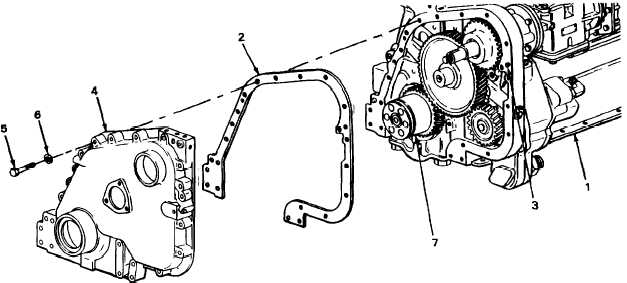
4. Cylinder block (1)
Crankshaft (7)
a.
Set dial indicator to zero.
b.
Using crankshaft barring tool, rotate
crankshaft and check dial indicator
reading for runout not to exceed 0.010
inch (0.25 mm).
5.
Gearcase cover (4)
Aline.
6. Gearcase cover (4)
Thirteen screws (5)
Using 1/2-inch drive 5/8-inch socket and
0 to 250 ft lb (0 to 350 N•m) torque wrench,
tighten to 45 to 50 ft lb (63 to 70 N•m).
T A 2 4 2 3 9 2
2-91
|
|