|
|
|
|

|
TM 5-2815-241-34&P
CYLINDER HEAD - CONTINUED
ACTION
LOCATION
ITEM
REMARKS
DISASSEMBLY
WARNING
Extreme care must be taken when releasing springs under pressure. Injury to personnel
could result.
NOTE
Steps given are typical for all three cylinder heads.
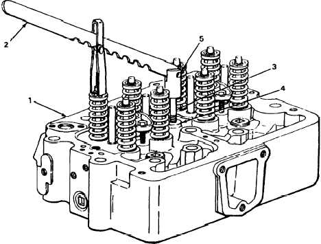
1. Cylinder head (1)
Valve spring
compressor (2)
a.
Screw stud (3) into rocker lever cap-
screw hole (4).
b.
Install valve spring compressor pivot
head (5) on stud (3).
T A 2 4 2 4 5 1
2-177
|
|
|
|
|
Privacy Statement -
Copyright Information. -
Contact Us