TM 5-2815-241-34&P
ANEROID CONTROL VALVE - CONTINUED
ACTION
LOCATION
ITEM
REMARKS
ASSEMBLY
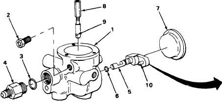
16. Aneroid control
valve (1)
17.
18.
19.
20.
New gasket (3) and
check valve (4)
Air filter (2)
Shaft valve (5)
and new preformed
packing (6)
Side cover (7)
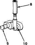
Shaft valve (5) and
bellows actuating
shaft (8)
a.
install new gasket on check valve.
b.
Put check valve into position, and using
7/8-inch open-end wrench, tighten.
Put in position, and using 7/16-inch box-
end wrench, tighten.
Put new packing on shaft valve.
Put in position and, using plastic-faced
hammer, tap in place.
Lower bellows actuating shaft into aneroid
control valve body (1) alining hole (9) with
pin (10) on shaft valve as shown.
NOTE
Before performing step 21, dip bellows in lubricating oil to ensure pliability when
assembling.
T A 2 4 2 6 0 6
2-402
|
|


