TM 5-2815-241-34&P
ANEROID CONTROL VALVE - CONTINUED
ACTION
LOCATION
ITEM
REMARKS
21.
22.
23.
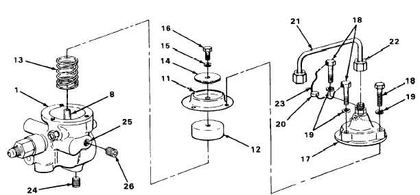
Bellows cover (17)
24.
Three screws (18),
Position new lockwashers and screws as
and three new
shown, and using 7/16-inch box-end
lockwashers (19)
wrench, tighten.
25.
26.
Aneroid control
valve body (1)
Bellows (11), piston
(12), spring (13),
and bellows actuating
shaft (8)
Place bellows, piston, and spring on
bellows actuating shaft.
Bellows washer (14),
new lockwasher (15)
and screw (16)
a.
Place bellows washer on bellows (11).
b.
Position new lockwasher and screw, and
using 7/16-inch box-end wrench,
tighten.
Aline bellows (11) and bellows cover with
holes in aneroid control valve (1).
Lead seal (20),
a.
Connect new lock wire to screws and
tubing (21), tubing
crimp on lead seal.
nut (22), and new
b.
Position tubing, and using 9/16-inch
lock wire (23)
box-end wrench, tighten tubing nut.
Pipe plug (24), pipe
plug hole (25), and
pipe plug (26)
a.
Using 3/16-inch hex wrench, screw in
and tighten pipe plug (24).
b.
Fill pipe plug hole with lubricating oil
until oil leaks from hole.
c.
Using 3/16-inch hex wrench, screw in
and tighten pipe plug (26).
T A 2 4 2 6 0 7
2-403
|
|