TM 5-3895-360-13
13-3. LOWER UNIT MAINTENANCE (’VR11C) (Con’t).
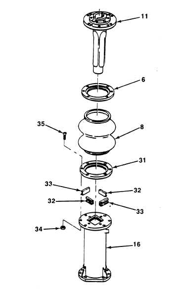
Figure 13-8. Dust Boot Replacement (VR11C).
f.
g.
h.
i.
j.
k.
l.
Install piston ring (23) on piston (24).
Install spacer ring (22), piston (24), spacer ring (25),
and new locknut (26) on piston rod (5).
NOTE
Refer to Figure 13-6, Lower Unit Lower Springs
Replacement (VR11C), for steps h through j.
Position three springs (17, 18, and 19) in lower unit
housing (16).
Position new preformed packing (20) and base plate
(15) on lower unit housing (16) and install two mach-
ine bolts (13) evenly.
Install two screws (21) on base plate (15).
NOTE
Refer to Figure 13-5, Lower Unit Disassembly
Bolts Installation and Removal (VR11C), for
steps k and l
Remove two machine bolts (13) from base plate
(15).
Install two screws (14) on base plate (15).
INSTALLATION
NOTE
Refer to Figure 13-4, Lower Unit Replacement
(V11C), for steps a through d.
a. Position new preformed packing (12) and lower unit
NOTE
(1) on gearcase (3).
Refer to Figure 13-7, Piston Rod Replacement
b. Push down on guide tube(11) and install pin (1 O) and
(VR11C), for steps d through g.
two expansion plugs (4) on piston rod (5).
d. Install sleeve bushing (30) on piston rod (5).
c. install guide tube (11) on gearcase (3) with four
screws (9).
e. Install piston rod (5), spacer (29), and two springs
d. Install upper boot ring (6) and guide tube (11) on
(27 and 28) in lower unit housing (16).
gearcase (3) with six screws (7).
13-7
|
|