P A R 75. S T E P S 2 7 - 3 0
DlSASSEMBLY
C H A P 5, SEC II
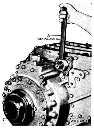
Figure 91 (Step 27)
Figure 93 (Step 29)
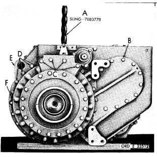
Attach sling (A), and, using a 5/8-inch wrench,
remove 27 bolts (B), four bolts (C) and three
bolts (D) and 34 lock washers. Remove lifting
b r a c k e t ( E ) . U s e t h r e e b o l t s ( B ) a s j a c k-
screws in holes (F), to loosen output housing.
U s i n g w r e n c h ( A ) , a p p l y t r a n s m i s s i o n r i g h t
b r a k e .
U s i n g a l - i n c h w r e n c h , r e m o v e b o lt
(B), lock plate (C) and output coupling (D).
Figure 94 (Step 30)
Figure 92 (Step 28)
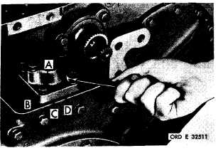
U s i n g a 9 / 1 6 - i n c h w r e n c h , r e m o v e s i x b o l ts
(A) and lock washers (B) retaining accumulator
body (C). Remove accumulator body and gas-
ket (D).
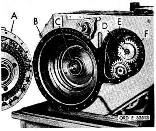
Remove right-output housing assembly (A) and
g a s k e t ( B ) . R e m o v e o u t p u t t r a n s f e r d r i ve
s h a f t ( C ) . U s i n g a 1 - i n c h w r e n c h , r e m o ve
b o l t ( D ) a n d l o c k p l a t e ( E ) r e t a i n i n g b r a ke
coolant oil pump drive gear (F).
9
1
|
|