*C2
*C2
C H A P 5, S E C V l l
I N P U T T R A N S F E R H O U S I N G R E B U I L D
PAR 9 7 - 9 9
Section VII.
I N P U T T R A N S F E R H O U S I N G — R E B U I LD
9 7 . D E S C R I P T I ON
Refer to par. 8 for the description of the
input transfer housing.
9 8 . D I S A S S E M B L Y ( f i g . 3 7 3 , f o l d - o u t 2)
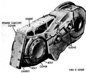
a . Using a 9/16-inch wrench, remove 10
bolts and lock washers that retain the power
t a k e - o f f c o v e r ( f i g . 1 5 0 ) . R e m o v e t h e c o v er
and gasket.
b . U s i n g 9 / 1 6 - i n c h w r e n c h , r e m o v e
t w e l v e 3 / 8 - 2 4 x 1 - l / 4 - i n c h b o l t s w i t h l o ck
washers. Remove transfer housing cover and
gasket (fig. 150).
c . Do not remove inserts 137, 140, 112,
1 1 3 a n d 1 2 2 ( f i g . 3 7 3 , f o l d - o u t 2 ) , b u s h i ng
assembly 118, or sleeves 119, 120, 134, 136,
or 139 from input transfer housing assembly
1 1 1 , u n l e s s r e p l a c e m e n t i s n e c e s s a r y . I f
necessary to remove a bushing or insert, refer
to par. 72 for the proper procedure. Bushing
assembly 118 is threaded and may be removed
with a wrench.
d . I f i t i s n e c e s s a r y t o r e m o v e s l e e v e s,
remove all of the sleeves in the housing, by
pressing or cutting out, except sleeve 139.
Figure 150. Input transfer housing
1
1
0
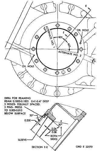
e. If necessary to remove the input trans-
f e r d r i v e g e a r s u p p o r t s l e e v e 1 3 9 , d r i l l o ut
pins 138. Use a drill bit slightly larger than
3/16-inch and drill only deep enough to free
the sleeve. Press the sleeve from the housing.
f . R e m o v e a n y p i p e p l u g s ( f i g . 1 5 0 ) , if
necessary, to aid in the cleaning of the oil pas-
sages in the housing.
9 9 . C L E A N I N G
d a t i o n s.
R e f e r t o p a r . 7 1 f o r c l e a n i n g r e c o m m e n -
Figure 151. Location of input transfer drive gear
support sleeve retaining pins
|
|