CHAP 5, SEC XIII
OUTPUT SUPPORT ASSEMBLY—REBUILD
PAR 127-128
Section XIII. OUTPUT SUPPORT ASSEMBLY—REBUILD
127. DESCRIPTION
e . Remove retaining ring that retains
output support bearing (fig. 155). Remove
T h e o u t p u t s u p p o r t i s a m a c h i n ed
bearing from the support.
steel casting. It serves as a support for
the transmission output drive assembly.
f . Remove retaining ring that retains
speedometer gear assembly and bearing in
the output support assembly (fig. 155).
128. DISASSEMBLY (fig. 374, fold-out 3)
Tap the gear assembly and bearing out of
the support.
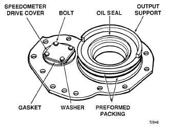
a . Remove two preformed packings
from hub of the output support assembly
(fig. 154).
b . Do not remove oil seal unless re-
placement is necessary (fig. 154). If neces-
sary, hook it out with a “heeled” tool.
c . Using a 7/16-inch socket wrench,
remove four bolts and lock washers from
the speedometer drive cover (fig. 154).
Note. This cover not used when
the speedometer is connected.
d . R e m o v e s p e e d o m e t e r d r i v e c o v er
and gasket (fig. 154).
Figure 154. Output support assembly --
outer side
118
|
|