PAR 128-131
O U T P U T S U P P O R T R E B U I LD
C H A P 5, SEC X I I I
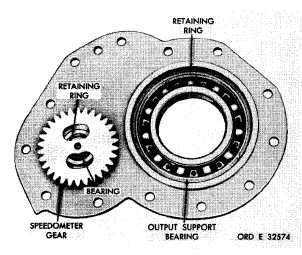
Figure 155. Output support assembly—inner side
g . R e m o v e r e t a i n i n g r i n g 7 1 ( f i g . 3 7 4,
fold-out 3) that retains bearing 69 on speedo-
m e t e r g e a r a s s e m b l y 6 5 . R e m o v e t h e b e a r-
ing from the gear.
h . Remove retaining ring 70 that retains
adapter 74 in output support 8.
i . Press adapter 74 and locating ball 73
from the support.
j . Do not remove oil seal 75 from adapt-
e r 7 4 u n l e s s r e p l a c e m e n t i s n e c e s s a r y . I f
necessary, tap the oil seal from the adapter.
1 2 9 . C L E A N I NG
Refer to par. 71 for cleaning recommen-
d a t i o n s.
1 3 0 . I N S P E C T I O N A N D R E P A IR
R e f e r t o p a r . 7 2 f o r g e n e r a l i n s p e c t i o n
a n d r e p a i r r e c o m m e n d a t i o n s . R e p a i r a n d r e-
b u i l d p o i n t s o f m e a s u r e m e n t f o r f i t s , c l e a r-
ances and wear limits are indicated by small,
lower case letters in fig. 374, fold-out 3. Re-
fer to par. 236 for wear limits information.
1 3 1 . A S S E M B L Y ( f i g . 3 7 4 , f o l d - o u t 3)
a . If oil seal 75 was removed from adapt-
e r 7 4 , p r e s s a n e w s e a l , l i p s i d e f i r s t , i n to
the adapter. Seat the seal firmly against its
shoulder in the adapter.
b . Install adapter 74 and locating ball 73
into output support 8 and secure with retaining
ring 70.
c . Place retaining ring 68 on the shaft of
gear assembly 65, next to the gear web. In-
stall bearing 69 onto speedometer gear assem-
bly 65 and secure with retaining ring 71.
d . Install speedometer gear with bearing
and retaining ring into support adapter and
secure with the retaining ring (fig. 155).
e . Install the output support bearing and
secure with the retaining ring (fig. 155).
f . I n s t a l l s p e e d o m e t e r d r i v e c o v e r a nd
g a s k e t o n o u t p u t s u p p o r t ( f i g . 1 5 4 ) . S e c u re
the cover with four 1/4-20 bolts and lock wash-
e r s . T i g h t e n t h e b o l t s t o 9 - 1 1 p o u n d - f e e t
t o r q u e.
g . I f o i l s e a l w a s r e m o v e d , i n s t a l l n ew
replacement, lip side of the seal toward the
inside of the support (fig. 154). Use replacer
8351210 and press the new seal in until it is
seated firmly against its shoulder in the sup-
p o r t.
h . Install two preformed packings on the
hub of the support (fig. 154).
1 1 9
|
|