*C2
CHAP 5, SEC X VI
1 4 4 . C L E A N I NG
Refer to par.
dations.
R I G H T O U T P U T R E B U I LD
PAR 1 4 4 - 1 46
71 for cleaning recommen-
1 4 5 . I N S P E C T I O N A N D R E P A IR
R e f e r t o p a r . 7 2 f o r g e n e r a l i n s p e c t i on
and repair recommendations. Repair and re-
b u i l d p o i n t s o f m e a s u r e m e n t f o r f i t s , c l e a r -
ances and wear limits are indicated by small,
l o w e r c a s e l e t t e r s i n f i g . 3 8 1 , f o l d - o u t 1 0.
Refer to pars. 243 and 244 for wear limits in-
f o r m a t i o n.
1 4 6 . A S S E M B L Y ( f i g . 3 8 1 , f o l d - o u t 1 0)
a . Install any plugs that were removed
f r o m t h e e n d c o v e r ( f i g . 1 6 1 ) . I n s t a l l p r e -
formed packing 59 (fig. 381, fold-out 10) into
end cover 48.
b . Install bearing 70 into sleeve 61.
c . Install sleeve 61 with bearing 70 and
gasket 60 into end cover 48. Secure retainer
with eight 3/8-16 x 1 self-locking bolts 62.
d . I n s t a l l b e a r i n g a s s e m b l y 7 2 i n t o t he
e n d c o v e r h u b 7 3 . B e s u r e t h e b e a r i n g is
firmly seated in the hub.
e . Install retaining ring 71 that retains
bearing 72.
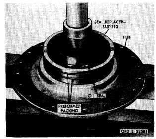
f. Install two preformed packings on end
cover hub (fig. 162).
g . U s i n g s e a l r e p l a c e r 8 3 5 1 2 1 0 , i n s t a ll
oil seal in end cover hub (fig. 162).
N o t e . Spring side of oil seal should
be toward the inside of the hub. Be
sure seal is seated.
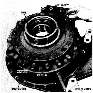
h . Install hub assembly and gasket onto
end cover. Secure the hub with nineteen 7/16-
14 x 1-1/2 cap screws and lock washers (fig.
163). Tighten the cap screws to 42-50 pound-
feet torque.
i . I n s t a l l s t e e r c l u t c h p i s t o n a s s e m b l y ,
alining the bleed hole as shown. Install guide
bolt 8351231 (fig. 164).
j . U s i n g s l i n g 7 0 8 3 7 7 8 a n d t h r e e 7 / 1 6-
14 bolts, install the steer clutch anchor (fig.
165).
N o t e . Oil holes in anchor and end
cover must be alined as shown.
k . Install the spacer (fig. 166).
Figure 162. Installing oil seal in end cover hub
Figure 163. Installing end cover hub
1 2 4
|
|


