*C2
*C2
*C2
*C2
PAR 1 4 6
R I G H T O U T P U T R E B U I L D
C H A P 5, SEC X V I
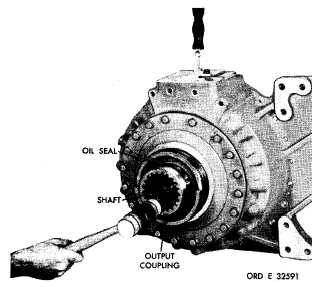
Figure 172. Installing output coupling
n . Install nine steer clutch piston return
springs (fig. 168).
o . Using sling 7083778 and three 7/16-14
b o l t s , i n s t a l l c l u t c h r e a c t i o n p l a t e a s s e m b ly
(fig. 169).
N o t e. Aline index mark on plate with
mark on end cover.
p . I n s t a l l t h e r i g h t - b r a k e a n c h o r r i ng
(fig. 170).
q . Install 18 bolts (two different lengths)
that retain the brake anchor ring (fig. 170).
Remove guide bolt 8351231 and install remain-
ing bolt. Torque the bolts to 42-50 pound-feet.
r . Using hoist and sling 8351496, install
the right-steer planetary carrier and brake hub
a s s e m b l y ( f i g . 1 7 1 ).
s . I n s t a l l o u t p u t c o u p l i n g o n t o c a r r i er
output shaft (fig. 172).
Caution: Rotate output shaft and tap
coupling lightly with soft mallet, being
careful not to damage the oil seal.
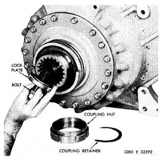
t . Install lock plate and 3/4-16 x 2-3/4
self-locking bolt (fig. 173). Tighten bolt only
finger-tight at this time. Temporarily install
coupling retainer and coupling nut.
Figure 173. Installing output coupling lock plate and
retaining bolt
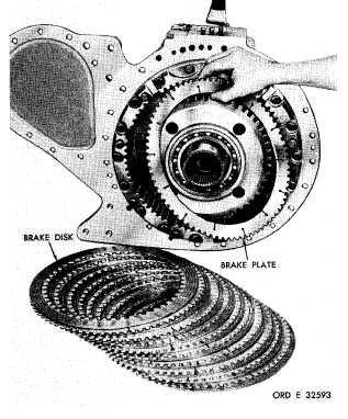
Figure 174. Installing right-brake plates and disks
u . Install 10 internal- and 10 external-
splined brake plates and disks, beginning with
an external-splined brake plate (fig. 174).
1 2 7
|
|