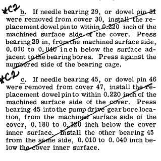
*C2
*C2
*C2
C H A P 5, SEC X V II
B R A K E C O O L A N T O I L P U M P R E B U I LD
PAR 147-151
Section XVII.
B R A K E C O O L A N T O I L P U M P — R E B U I LD
1 4 7 . D E S C R I P T I ON
R e f e r t o p a r . 2 4 f o r d e s c r i p t i o n o f t h e
brake coolant oil pump.
148. DISASSEMBLY (fig. 384, fold-out 13)
a . U s i n g a 9 / 1 6 - i n c h w r e n c h , r e m o ve
three cap screws 60 with three lock washers
59 and three self-locking bolts 53 securing the
brake coolant pump assembly 20 to the brake
coolant pump manifold 56. Remove the pump
assembly and gasket 54.
b . Remove two sets of brake coolant oil
check valve components (64 through 68).
c . U s i n g l / 2 - i n c h w r e n c h , r e m o v e s e l f-
locking bolt 51 securing drive gear shroud 48
and shroud plate 50 to the pump. Remove the
shroud and plate. Straighten and remove lock
pin 42 from gear 49. Remove the gear.
d . U s i n g a l / 2 - i n c h w r e n c h , r e m o v e 14
self-locking bolts 27 and 52, securing the two
cover assemblies 28 and 44 to the coolant oil
pump body 32. Remove the cover assemblies.
e . Do not remove the needle bearing as-
semblies 29 and 45 or dowel pins 31 and 46
from covers 30 and 47 unless replacement is
n e c e s s a r y . I f n e c e s s a r y , p r e s s o r d r i v e o ut
the bearings or pins.
f . R e m o v e , a s a u n i t , i d l e r g e a r s h a f t
22, pump drive shaft 40, two oil pump idler
gears 21 and 26, two drive gears 33 and 43,
and the two oil pump separator plate assem-
blies 23 and 36 from the pump body.
g . R e m o v e i d l e r g e a r s 2 1 a n d 2 6 f r om
their shaft 22.
h . Remove oil pump drive gears 33 and
43 and keys 34 and 41 from the pump drive
shaft 40.
i . R e m o v e t w o r e t a i n i n g r i n g s 3 5 f r om
oil oil pump idler 22 and drive 40 gear shafts.
j. Remove separator plate assemblies 23
and 36 from shafts 22 and 40.
1
2
8
k . Do not remove needle bearings 25 and
37 from separator plates 24 and 38 unless re-
p l a c e m e n t i s n e c e s s a r y . I f n e c e s s a r y , p r e ss
b e a r i n g s f r o m p l a t e s.
l . Do not remove retaining rings 39 from
oil pump idler 22 and drive 40 gear shafts un-
l e s s r e p l a c e m e n t i s n e c e s s a r y.
1 4 9 . C L E A N I NG
Refer to par. 71 for cleaning recommen-
dations.
1 5 0 . I N S P E C T I O N A N D R E P A IR
R e f e r t o p a r . 7 2 f o r g e n e r a l i n s p e c t i on
and repair recommendations. Repair and re-
b u i l d p o i n t s o f m e a s u r e m e n t f o r f i t s , c l e a r-
ances and wear limits are indicated by small,
l o w e r c a s e l e t t e r s i n f i g . 3 8 4 , f o l d - o u t 1 3.
Refer to par. 247 for wear limits information.
1 5 1 . A S S E M B L Y ( f i g . 3 8 4 , f o l d - o u t 1 3)
a . If needle bearings 25 and 37 were re-
moved from separator plates 24 and 38, install
replacements
0.320-inch
below
the
surface
a d j a c e n t t o t h e b e a r i n g b o r e s . P r e s s o n t h e
numbered side of the bearing cage.
|
|


