CHAP 5, SEC X X
B R A K E A N C H O R R I N G , C L U T C H R E A C T I O N P L A T E R E B U I L D
PAR 1 6 2 - 1 65
Section XX. LEFT- AND RIGHT-BRAKE ANCHOR RING AND CLUTCH
R E A C T I O N P L A T E A S S E M B L I E S — R E B U I LD
1 6 2 . D E S C R I P T I O N
Refer to pars. 16 and 17 for the descrip-
tion of the left- and right-brake anchor ring
and clutch reaction plate assemblies.
163. DISASSEMBLY (figs. 377 and 381,
fold-outs 6 and 10)
a . L e f t - a n d R i g h t - b r a k e A n c h o r R i ng
A s s e m b l i e s
N o t e . T h e l e f t - a n d r i g h t - b r a k e
anchor ring assemblies are identical,
therefore, the following disassembly
procedures apply to either assembly.
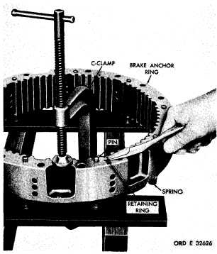
(1) With the aid of a C-clamp, compress
the brake release springs, and remove two re-
taining rings from the brake return guide pins
(fig. 207).
Figure 207. Removing (or installing) brake return
guide pin retaining ring
( 2 ) R e m o v e t h e g u i d e p i n s a n d r e t u rn
springs (fig. 207).
(3) Remove the remaining seven retain-
ing rings, springs and guide pin, in the same
manner as described in (1) and (2), above.
b . L e f t - a n d R i g h t - c l u t c h R e a c t i on
P l a t e A s s e m b l i es
N o t e . The left- and right-clutch re-
action plate assemblies are identical,
therefore, the following disassembly
procedures apply to either assembly.
T h e f o l l o w i n g d e s c r i b e s t h e d i s a s -
sembly
of
the
left-clutch
reaction
p l a t e a s s e m b l y .
(1) Do not disassemble clutch reaction
plate assembly unless replacement of parts is
n e c e s s a r y . I f n e c e s s a r y , r e m o v e t h r e e s e l f-
locking bolts 72 (fig. 377, fold-out 6), using
a l / 2 - i n c h w r e n c h.
( 2 ) R e m o v e s l e e v e 7 1.
(3) Remove two preformed packings 70
from sleeve 71.
1 6 4 . C L E A N I NG
Refer to par. 71 for cleaning recommen-
d a t i o n s.
1 6 5 . I N S P E C T I O N A N D R E P A IR
R e f e r t o p a r . 7 2 f o r g e n e r a l i n s p e c t i on
and repair recommendations. Repair and re-
b u i l d p o i n t s o f m e a s u r e m e n t f o r f i t s , c l e a r-
ances and wear limits are indicated by small,
lower case letters in figs. 377 and 381, fold-
outs 6 and 10. Refer to pars. 240 and 244 for
wear limits information.
1
4
2
|
|