PAR 1 6 6 - 1 68
L E F T , R I G H T O U T P U T C L U T C H E S R E B U I L D
C H A P 5, SEC X X I
166. ASSEMBLY (figs. 377 and 381,
fold-outs 6 and 10)
a . L e f t - a n d R i g h t - b r a k e A n c h or
—
R i n g A s s e m b l i es
N o t e . The left- and right-brake anchor
r i n g a s s e m b l i e s a r e i d e n t i c a l , t h e r e -
fore the following assembly procedures
apply to either assembly.
(1) Install the brake return guide pin and
spring in the brake anchor ring (fig. 207).
( 2 ) U s i n g a C - c l a m p , c o m p r e s s t h e
brake return spring, and install the retaining
ring (fig. 207).
(3) Install the remaining eight brake re-
turn guide pins, springs and retaining rings
in the same manner as described in (1) and (2),
a b o v e.
Section
1 6 7 . D E S C R I P T I ON
Refer to par. 16 for
b . L e f t - a n d R i g h t - c l u t c h R e a c t i on
P l a t e A s s e m b l i e s
Note.
The left- and right-clutch re-
action plate assemblies are identical,
therefore the following assembly pro-
c e d u r e s a p p l y t o e i t h e r a s s e m b l y.
However, the following describes the
a s s e m b l y o f t h e l e f t - c l u t c h r e a c t i on
p l a t e a s s e m b l y.
( 1 ) I n s t a l l t w o p r e f o r m e d p a c k i n g s 70
(fig. 377, fold-out 6) on sleeve 71.
( 2 ) I n s t a l l s l e e v e 7 1 w i t h p r e f o r m e d
packings 70 in clutch reaction plate 67.
(3) Secure sleeve 71 with three 5/16-18
x 1 self-locking bolts 72. Torque the bolts to
17-20 pound-feet.
X X I . L E F T - A N D R I G H T - O U T P U T C L U T C H E S — R E B U I LD
the description of the
left- and right-output clutches.
168. DISASSEMBLY (figs. 377 and 381,
fold-outs 6 and 10)
N o t e . The left- and right-output clutch
a s s e m b l i e s a r e i d e n t i c a l , t h e r e f o r e t he
following disassembly procedures apply
t o e i t h e r a s s e m b l y . A l l r e f e r e n c e s t o
exploded views are to fig. 377, fold-out
6, illustrating the left assembly.
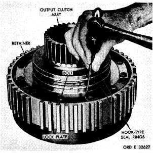
a . Remove two hook-type seal rings from
the hub of the output clutch assembly (fig. 208).
b . U s i n g a h a m m e r a n d p u n c h , f l a t t en
the corners of the lock plates on the output
clutch assembly (fig. 208).
Figure 208. Straightening corners of output clutch
lock plates
1
4
3
|
|


