PAR 1 9 1
L O W P L A N E T A R Y A N D O U T P U T S H A F T R E B U I LD
C H A P 5, SEC X X V
Figure 221. Alining pinion and component parts in
planetary carrier
Figure 219. Removing spindle lock pin
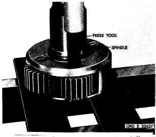
Figure 222. Installing planetary carrier spindle
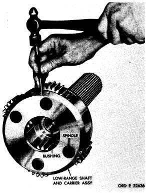
Figure 220. Removing planetary carrier spindle
e . Insert alining tool 8351209, with wash-
er and spacer, into the pinion.
f . I n s t a l l a s p a c e r 2 9 o r 3 2 ( f i g . 3 7 6 ,
fold-out 5) over the alining tool, then a thrust
washer 28 or 33. Remove the alining tool.
g . Slide pinion 30 and its related parts
into location in carrier 27 from which it was
r e m o v e d . U s i n g a l i n i n g t o o l 8 3 5 1 2 0 9 , a l i ne
t h e p i n i o n , w a s h e r s a n d r o l l e r s . R e f e r to
fig. 221. Remove the alining tool.
h . I n s t a l l s p i n d l e r e p l a c e r 8 3 5 1 2 6 6 o n
1 51
|
|