*C2
*C2
*C2
C H A P 5, SEC X X V I
I N T E R M E D I A T E P L A N E T A R Y , L O W R I N G G E A R R E B U I LD
PAR 191-195
the planetary carrier and position the spindle
for installation. See fig. 222.
N o t e . Be sure that the slot on the
spindle is indexed properly with its
lock pin bore in the carrier.
i.
With
a
press
and
spindle
replacer
8351266, install planetary carrier spindle (fig.
222). The spindle replacer will bottom against
the carrier when the spindle is properly posi-
tioned in the carrier.
j . U s i n g a h a m m e r a n d p u n c h , i n s t a l l
t h e p l a n e t a r y c a r r i e r s p i n d l e l o c k p i n ( f i g .
2 1 9 ) . D r i v e t h e p i n i n 0 . 0 3 0 t o 0 . 0 6 0 b e l o w
the surface of the carrier. Stake metal over
the pin.
S e c t i o n X X V I . I N T E R M E D I A T E - R A N G E P L A N E T A R Y A N D L O W - R A N G E RING GEAR — REBUILD
1 9 2 . D E S C R I P T I O N
Refer to pars. 12 and 13 for the descrip-
tion of the intermediate-range planetary and
low-range ring gear.
1 9 3 . D I S A S S E M B L Y ( f i g . 3 7 6 , f o l d - o u t 5)
N o t e . All related items not covered
in a through d , below, were removed
from the transmission as outlined in
par. 75, steps 116, 123 and 124. No
further disassembly of these parts is
r e q u i r e d .
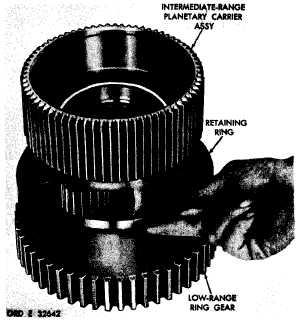
a . Remove retaining ring that retains the
i n t e r m e d i a t e - r a n g e p l a n e t a r y c a r r i e r a s s e m-
bly in the low-range ring gear (fig. 223). Re-
m o v e t h e c a r r i e r a s s e m b l y .
b . U s i n g a h a m m e r a n d p u n c h , r e m o ve
four planetary carrier spindle lock pins (fig.
2 2 4 ) .
c . Using a press and a piece of 3/8-inch
drill rod approximately 6 inches long, or other
s u i t a b l e p r e s s t o o l , r e m o v e f o u r p l a n e t a ry
spindles from the carrier (fig. 225).
d . R e m o v e p l a n e t a r y c a r r i e r p i n i o n s,
spacers, thrust washers and bearing rollers
from the carrier (fig. 225).
1
5
2
1 9 4 . C L E A N I N G
Refer to par. 71 for cleaning recommen-
d a t i o n s.
1 9 5 . I N S P E C T I O N A N D R E P A IR
R e f e r t o p a r . 7 2 f o r g e n e r a l i n s p e c t i o n
Figure 223. Removing (or installing) retaining ring
that retains intermediate-range planetary carrier assembly
|
|