P A R 227, STEPS 3 1 - 3 4
A S S E M B L Y
C H A P 5, SEC X X X I II
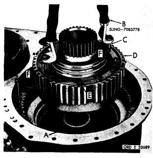
Figure 270 (Step 31)
I n s t a l l s p a c e r ( A ) , f l a n g e d e n d d o w n . U s i ng
sling (B) and two 5/16-24 bolts (C), install the
left-output clutch assembly (D). Remove sling,
and tap the assembly down while rotating it.
Install two remaining 5/16-24 x 5/8 bolts (E).
Using a l/2-inch wrench, torque the bolts to
14-18 pound-feet. Bend corners of lock strips
(F) against bolt heads.
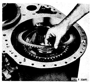
Figure 271 (Step 32)
Install nine geared steer clutch piston return
springs (A). Install an external-splined steer
clutch plate (B).
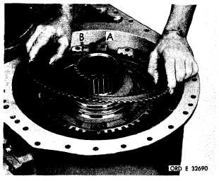
Figure 272 (Step 33)
Alternately install the remaining six internal-
(A) and six external-splined (B) steer clutch
p l a t e s , b e g i n n i n g w i t h a n i n t e r n a l - s p l i n e d
p l a t e.
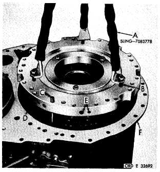
Figure 273 (Step 34)
U s i n g s l i n g ( A ) , t h r e e 7 / 1 6 - 1 4 b o l t s ( B ) a nd
the guide bolt (C), install the reaction plate as-
sembly (D). Note the location of the plugs (E)
in the assembly in relation to the housing (F).
1 7 1
|
|