*C2
C H A P 5, SEC X X X I I I
A S S E M B LY
P A R 2 2 7 , S T E P S 3 5 - 3 8
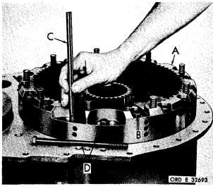
Figure 274 (Step 35)
I n s t a l l b r a k e a n c h o r a s s e m b l y ( A ) . I n s t a l l
sixteen 7/16- 14x 7-1/2 bolts (B) and one 7/16-
1 4 x 7 b o l t ( D ) . R e m o v e g u i d e b o l t ( C ) a n d
install remaining 7/16- 14 x 7 bolt (D). Using
a 5/8-inch wrench, torque the eighteen bolts
to 42-50 pound-feet.
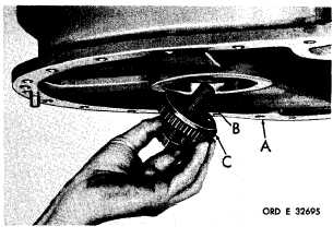
Figure 276 (Step 37)
Raise the transmission housing (A) and install
3/4-16
self-locking
bolt
(B)
and
lock
plate
(C)
into the end of the steer planetary carrier and
shaft assembly. Tighten bolt only finger-tight
at this time.
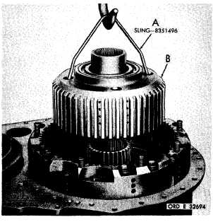
Figure 275 (Step 36)
Using hoist and sling (A), install the geared
s t e e r p l a n e t a r y c a r r i e r a n d s h a f t a s s e m b ly
(B). Remove the sling and tap the assembly
down while rotating it.
1 7 2
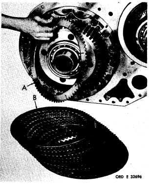
Figure 277 (Step 38)
Position the transmission housing on its bot-
tom. Install 10 external- (A) and 10 internal-
splined (B) left-brake plates alternately, be-
ginning with an external-splined plate (A).
|
|


