P A R 2 2 7 , S T E P S 3 9 - 4 2
A S S E M B L Y
C H A P 5, SEC X X X I II
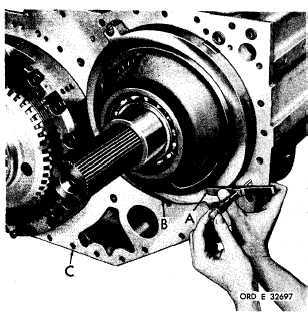
Figure 278 (Step 39)
Using a micrometer depth gage (A), measure
t h e d i s t a n c e f r o m t h e r e v e r s e - r a n g e s u p p o rt
housing (B) surface to the transmission hous-
ing (C) split-line surface. Record this dimen-
s i o n .
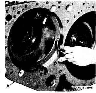
Figure 279 (Step 40)
Measure the depth of the counterbore in the
t r a n s m i s s i o n r e a r h o u s i n g ( A ) . R e c o r d t h is
d i m e n s i o n.
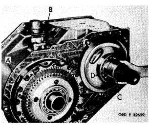
Figure 280 (Step 41)
U s i n g a m i c r o m e t e r,
m e a s u r e t h e t h i c k n e ss
o f t h e t r a n s m i s s i o n h o u s i n g - t o - r e a r h o u s i ng
g a s k e t ( A ) . R e c o r d t h i s d i m e n s i o n . I n s t a l l
gasket (A) on housing (B). Install spacer (C)
on hub of reverse-range carrier assembly (D).
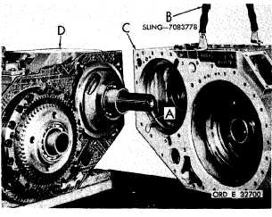
Figure 281 (Step 42)
T o o b t a i n s h i m p a c k ( A ) t h i c k n e s s , a d d t he
dimensions obtained above in Steps 40 and 41.
Add
an
additional
0.012-inch.
From
the
re-
sulting figure, subtract the dimension obtained
in Step 39.
T h i s d i f f e r e n c e i s t h e t h i c k n e ss
of the shim pack required. Three shim thick-
n e s s e s a r e a v a i l a b l e ( 0 . 0 0 8 , 0 . 0 1 0 , 0 . 0 12
approx.) Install the number of shims (A) re-
q u i r e d . U s i n g s l i n g ( B ) , i n s t a l l r e a r h o u s i ng
assembly (C) onto transmission main housing
a s s e m b l y ( D ).
1 7 3
|
|


