*C2
P A R 2 2 7 , S T E P S 4 7 - 5 0
A S S E M B L Y
C H A P 5, SEC X X X I I I
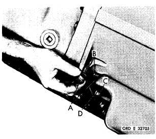
Figure 286 (Step 47)
Install two 1/2-13 x 1-3/4 bolts (A) and lock
w a s h e r s ( B ) . I n s t a l l t h e r e m a i n i n g 7 / 1 6 - 14
x 1-1/2 bolts (C) and lock washers (D). Tighten
a l l s p l i t l i n e b o l t s . T o r q u e 7 / 1 6 , 1 / 2 , a nd
5/8 bolts to 42-50, 67-80 and 117-140 pound-
f e e t , r e s p e c t i v e l y .
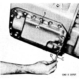
Figure 288 (Step 49)
Install the remaining thirteen 3/8-16 x 1-3/8
bolts (A) with lock washers (B) and four 3/8-16
x 2-1/2 bolts (C) with lock washers (D). Using
a 9/16-inch wrench, torque all of the bolts to
2 6 - 3 2 p o u n d - f e e t.
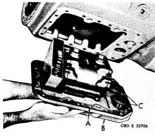
Figure 287 (Step 48)
Install gasket (A) on brake coolant oil pump
a n d m a n i f o l d a s s e m b l y ( B ) . N o t e . B e s u re
that valves (C) remain in proper position dur-
i n g i n s t a l l a t i o n o f a s s e m b l y ( B ) . I n s t a l l t wo
3/8-16 x 1-3/8 mounting bolts with lock wash-
ers to initially retain the pump and manifold
a s s e m b l y.
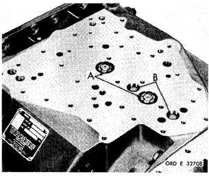
Figure 289 (Step 50)
U s i n g a 1 5 / 1 6 - i n c h s o c k e t w r e n c h , t i g h t en
the intermediate- and low-range clutch hous-
i n g n u t s ( A ) t o 1 3 4 - 1 6 0 p o u n d - f e e t t o r q u e.
Using a 9/16-inch wrench, tighten the inter-
m e d i a t e - , and low- and reverse-range clutch
piston housing bolts (B) to 26-32 pound-feet
t o r q u e .
1 7 5
|
|


